Resiliently mounted agricultural tool and implement therewith

a technology of agricultural tools and implements, which is applied in the field of agricultural tools, can solve the problems of crop residue plugging between the discs, damage to the blades, the shaft bearings, or the shaft mounting assemblies, and the force transmitted to the frame is still substantial, so as to reduce the damage to the assembly, prevent the formation of furrows, and increase the speed

Active Publication Date: 2011-06-09
SALFORD GRP INC
View PDF48 Cites 14 Cited by
  • Summary
  • Abstract
  • Description
  • Claims
  • Application Information

AI Technical Summary

Benefits of technology

[0020]The tillage assembly provides for mounting the tillage blades in a particular orientation relative to the ground and the direction of travel of the implement in order that forces acting on the assembly due to movement of the blade through the soil are balanced and resolve substantially vertically. This prevents an off-axis load from acting on the resilient element when the assembly is in use and allows the blade to track through the soil at a desired angle. Impact with obstacles, such as rocks, is desirably absorbed by deflection of the resilient element, the resilient portion of the support arm, and / or the elastomeric bushing(s) to thereby mitigating damage to the assembly.
[0021]Tillage implements comprising the tillage assemblies are able to operate at higher speeds than can usually be obtained for tillage implements, due to the absorption of impact energy. Typical operating speeds for such implements may be from 6 to 14 mph or 8 to 12 mph. The tillage implements may comprise a plurality of the tillage assemblies in substantially matched pairs, each pair comprising a first and second assembly. The tillage implements may comprise two or more rows of the tillage assemblies when seen in top view. The tillage implements may comprise three or more rows of the tillage assemblies when seen in top view. The tillage implements may comprise four or more rows of the tillage assemblies when seen in top view. There may be an even number of rows of the tillage assemblies. There may be a substantially equal number of first and second assemblies. One of the two rows may comprise one or more first assemblies and the other may comprise one or more second assemblies. The first and second assemblies may be provided in complementary pairs. The pairs may be arranged with one assembly on one row and the complementary assembly on an adjacent row. When provided with concave tillage blades, the first and second assemblies may be arranged on the two rows such that the concave sides of the tillage blades are oriented towards one another. In this configuration, the assemblies may be laterally spaced apart by a distance sufficient to permit soil thrown in one direction by a first tillage assembly to be thrown in an opposite direction by a second tillage assembly in order to substantially level the soil surface following tillage and / or substantially prevent furrow formation. The assemblies may be laterally spaced apart by a distance sufficient to prevent plugging of crop residue between the assemblies.

Problems solved by technology

However, since the entire shaft is forced to move upwardly and deflect when a single disc encounters and obstacle, the force transmitted to the frame is still substantial.
This can result in damage to the blades, the shaft bearings, or the shaft mounting assemblies.
An additional problem with disc harrows is that, due to the close spacing of the blades on the gang shaft, plugging of crop residue can occur between the discs.
This impedes operation of the implement and requires the farmer to stop and manually clean out the space between the discs before continuing.
This impedes the ability of the blade to turn the soil, which generally requires an angle with respect to the direction of travel.
Sideways loading would impart excessive wear to the bolt and ring arrangement that provides for the pivoting action of the assembly, leading to premature mechanical failure.
Use of a concave disc blade at an angle to the direction of travel would impart such an undesirable sideways loading.

Method used


Image

  • Resiliently mounted agricultural tool and implement therewith
  • Resiliently mounted agricultural tool and implement therewith
  • Resiliently mounted agricultural tool and implement therewith

Examples


Embodiment Construction

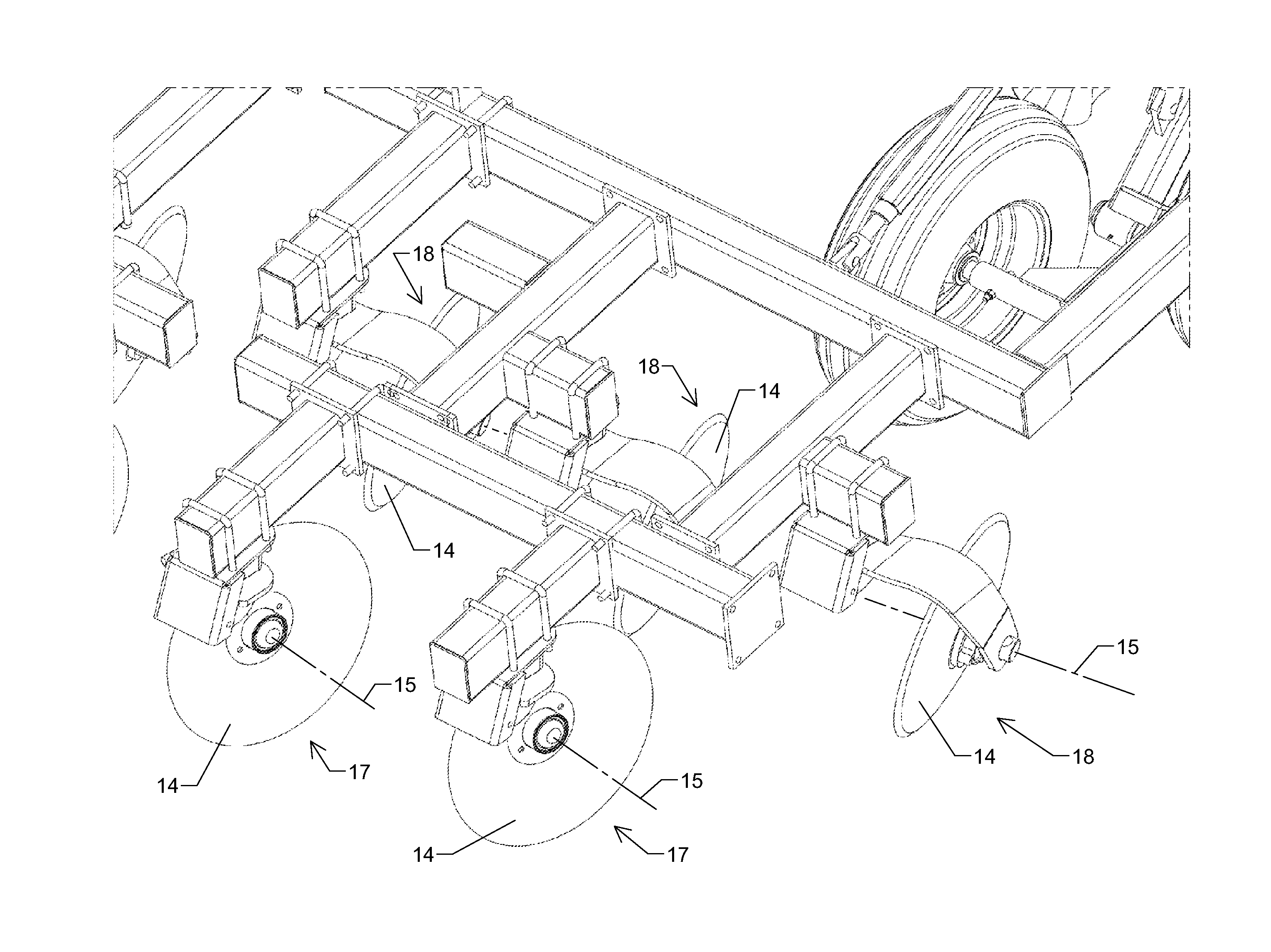
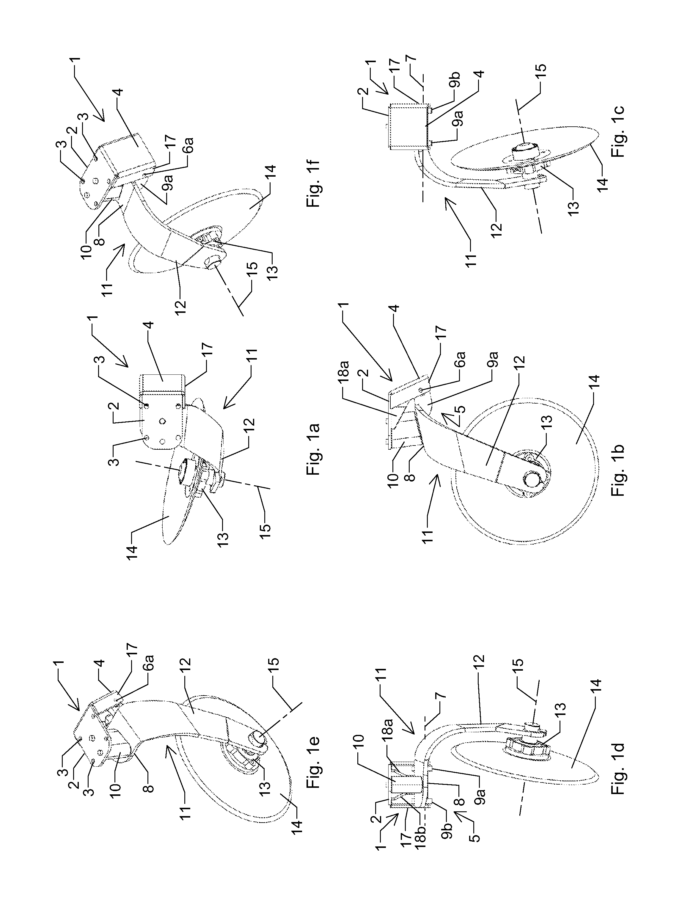
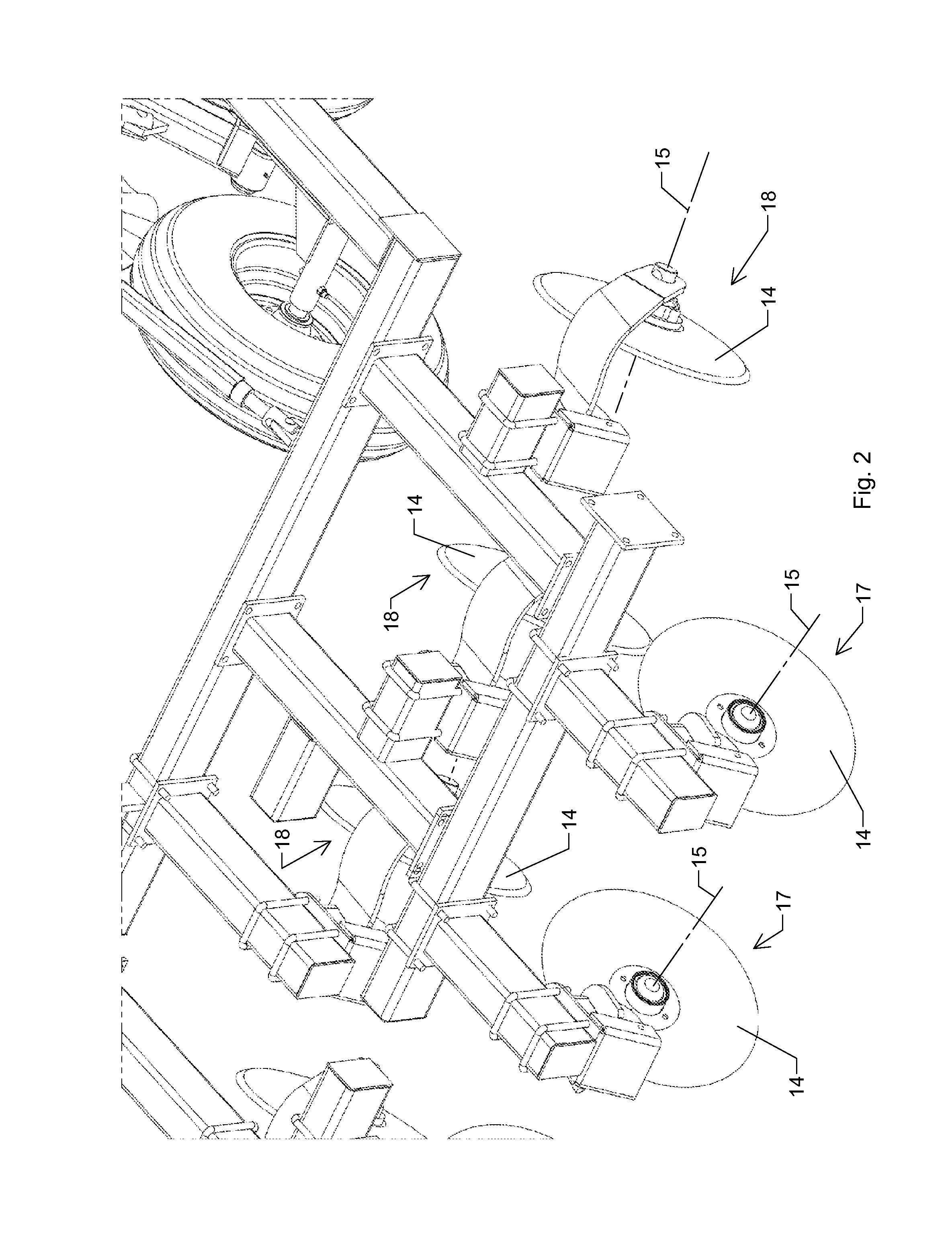
[0085]In describing the figures, like features are referred to by like reference numerals. Although not all features indicated on a particular drawing are necessarily described with reference to that drawing, all of the features are described with reference to at least one of the drawings.

[0086]Referring to FIGS. 1a-1f, an agricultural tool, in particular a tillage assembly, according to the invention comprises a mounting means 1 for securing the assembly to the underside of a frame member of an agricultural implement (not shown). The mounting means 1 includes a top plate 2 comprising a plurality of holes 3 for receiving an attachment means (not shown in this view, but normally comprising a pair of U-shaped hangers) for securing the mounting means 1 to the frame member. At the front end of the top plate 2 is provided a front plate 4 which may be attached to the top plate 2 or integrally formed therewith. The front plate 4 comprises a pair of side flanges 17 to provide it with additi...


PUM


Abstract

Disclosed are mounting means for agricultural tools, for example tillage assemblies, that comprise a resilient element and a horizontal pivot axis. This allows upward and rearward deflection of a tillage blade of the assembly in response to impact with obstacles. Tillage implements comprising the foregoing assemblies are also disclosed. In certain embodiments, the assemblies advantageously allow lateral deflection of at least a support arm of the assembly in response to impact with obstacles, which may be enhanced by providing a pivot means of the assembly with a resilient bushing. The resilient element and/or the resilient bushing may comprise elastomeric materials.

Description

CROSS-REFERENCE TO RELATED APPLICATIONS[0001]This application claims the benefit of U.S. Patent Application 61 / 285,176, filed Dec. 9, 2009, the contents of which are incorporated herein by reference.FIELD OF THE INVENTION[0002]The invention relates to agricultural tools that include mounting means, which permit upward deflection and optionally lateral deflection in response to impact with obstacles. In particular, the invention relates to tillage assemblies comprising mounting means with resilient elements that permit deflection of a tillage blade upwardly and optionally laterally, as well as tillage implements comprising the assemblies.BACKGROUND OF THE INVENTION[0003]Tillage implements, such as disc harrows, are known in agriculture for working the soil either following crop harvest or in preparation for spring planting. Typically, tillage implements work the soil at a depth of 4-6″ in an effort to turn over new soil and cover crop residue on the surface. This is sometimes known a...

Claims


Application Information

Patent Timeline
Patent Type & Authority Applications(United States)
IPC IPC(8): A01B61/00A01B15/16
CPCA01B21/086
Inventor GRAY, GEOF J.AVERINK, JOHN MARKROZENDAAL, JACOBUS A.RODIONOV, MIKHAIL
Owner SALFORD GRP INC
Why Eureka
Try Eureka