Digital control switching power supply unit

Active Publication Date: 2011-06-09
FUJI ELECTRIC CO LTD
View PDF8 Cites 11 Cited by
  • Summary
  • Abstract
  • Description
  • Claims
  • Application Information

AI Technical Summary

Benefits of technology

[0031]With the digital control switching power supply unit according to the invention, as the A/D converter circuit carries out a conversion operation controlled by a continuous analog signa

Problems solved by technology

With the digital control switching power supply unit, as a digital signal processing such as a PID calculation is necessary, a feedback control takes longer than with an analog control method, and it is known that there is a problem with transient response characteristics.
As the temporal margin is the delay time until an A/D conversion result is reflected in the PWM signal, the kind of excessive margin time shown in FIG. 14B delays feedback to the output of an A/D conversion result, and the transient response characteristics of the switching power supply unit are worsened considerably.
The following kinds of problem exist with the heretofore described heretofore known digital control switching power supply units.
Firstly, with the heretofore known first configuration example shown in FIG. 12, there is a problem in that a temporal margin is needed in the A/D conversion cycle, and there occurs a delay time until the PWM signal is generated based on the digital error signal e(n), wherein the error voltage between the output voltage

Method used


Image

  • Digital control switching power supply unit
  • Digital control switching power supply unit
  • Digital control switching power supply unit

Examples


first embodiment

[0047]Hereafter, a description will be given, while referring to the drawings, of a digital control switching power supply unit according to an embodiment of the invention.

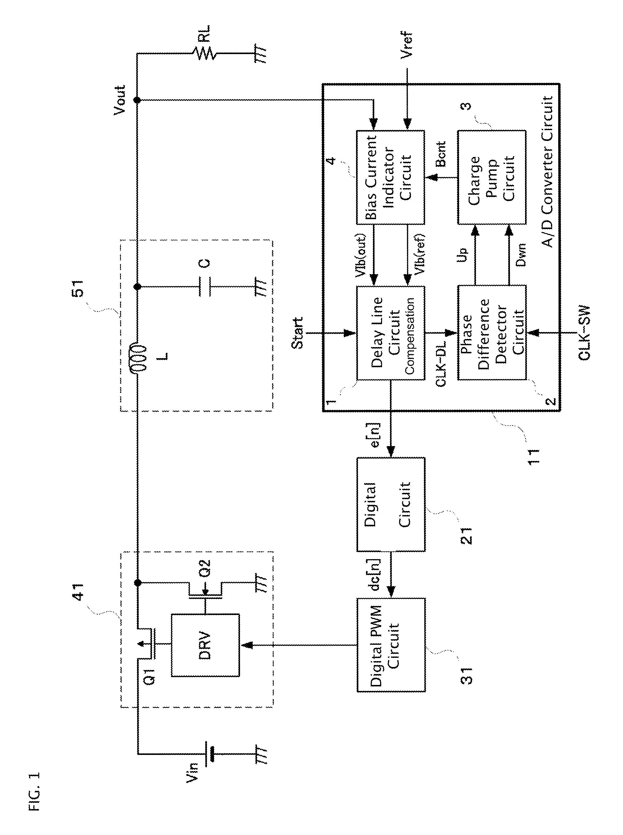
[0048]FIG. 1 is a block diagram showing a configuration of an embodiment of a digital control switching power supply unit according to the invention. The same reference numerals and characters will be given to places the same as those in the configuration examples of heretofore known digital control switching power supply units shown in FIGS. 12 and 15, and a detailed description will be omitted.

[0049]FIG. 1 is an example of a configuration of a digital control switching power supply unit of a voltage mode that converts an input voltage Vin into an output voltage Vout by controlling a switching element with a PWM signal, and is configured of an A / D converter circuit 11, a digital compensation circuit 21, a digital PWM circuit 31, a switching circuit 41, and an LC smoothing filter 51. An operation of the digital co...


PUM


Abstract

A digital control switching power supply unit includes an A/D converter circuit having a delay line circuit that has a delay element array whose delay time is controlled by a bias current, and that converts a current value into a digital signal using a signal transmission delay time, a phase difference detector circuit that detects a phase difference between a switching cycle and an A/D conversion cycle, a charge pump circuit that generates a control voltage in accordance with the phase difference, and a bias current indicator circuit that determines a bias current in accordance with an output voltage of the charge pump circuit and a result of a comparison of a detected value of the output voltage and a reference voltage, wherein the digital control switching power supply unit controls in such a way that the A/D conversion cycle is synchronized with the switching cycle.

Description

BACKGROUND OF THE INVENTION[0001]1. Technical Field[0002]The present invention relates to a switching power supply unit that performs a voltage conversion by carrying out a switching in accordance with a pulse width modulation signal (hereafter called a PWM signal), and in particular, relates to a digital control switching power supply unit having an analog-to-digital converter circuit (hereafter called an A / D converter circuit) preferable for control using a digital signal.[0003]2. Related Art[0004]FIG. 12 shows a first configuration example of a heretofore known common digital control switching power supply unit. The digital control switching power supply unit shown in FIG. 12, being a configuration example of a digital control switching power supply unit of a voltage mode wherein a switching element is controlled by a PWM signal and an input voltage Vin is converted to an output voltage Vout, is configured of a subtraction circuit Sub, an A / D converter circuit 12, a digital compe...

Claims


Application Information

Patent Timeline
IPC IPC(8): G05F1/10
CPCH02M3/157
Inventor SASAKI, MASAHIROKAWASHIMA, TETSUYA
Owner FUJI ELECTRIC CO LTD
Why Eureka
Try Eureka