Feedback circuit with feedback impedance modulation for improving power saving

Active Publication Date: 2011-06-09
SEMICON COMPONENTS IND LLC
View PDF5 Cites 12 Cited by
  • Summary
  • Abstract
  • Description
  • Claims
  • Application Information

AI Technical Summary

Benefits of technology

[0009]A feedback circuit with feedback impedance modulation is developed to reduce the power consumption of no-load and light-load conditions for power saving. It includes a compare circuit, a counter and a switching resistor circuit. The compare circuit receives a feedback signal of a power converter to compare the feedback signal with a threshold signal for generating a control signal. The feedback signal is correlated to a load condition of the power converter. The counter is coupled to the compare circuit and generates a modulation signal in response t

Problems solved by technology

However, the drawback of the prior art is that the feedback resistor RFB is the same resistance no matter what the loa

Method used


Image

  • Feedback circuit with feedback impedance modulation for improving power saving
  • Feedback circuit with feedback impedance modulation for improving power saving
  • Feedback circuit with feedback impedance modulation for improving power saving

Examples


Embodiment Construction

[0018]The following description is of the best-contemplated mode of carrying out the invention. This description is made for the purpose of illustrating the general principles of the invention and should not be taken in a limiting sense. The scope of the invention is best determined by reference to the appended claims.

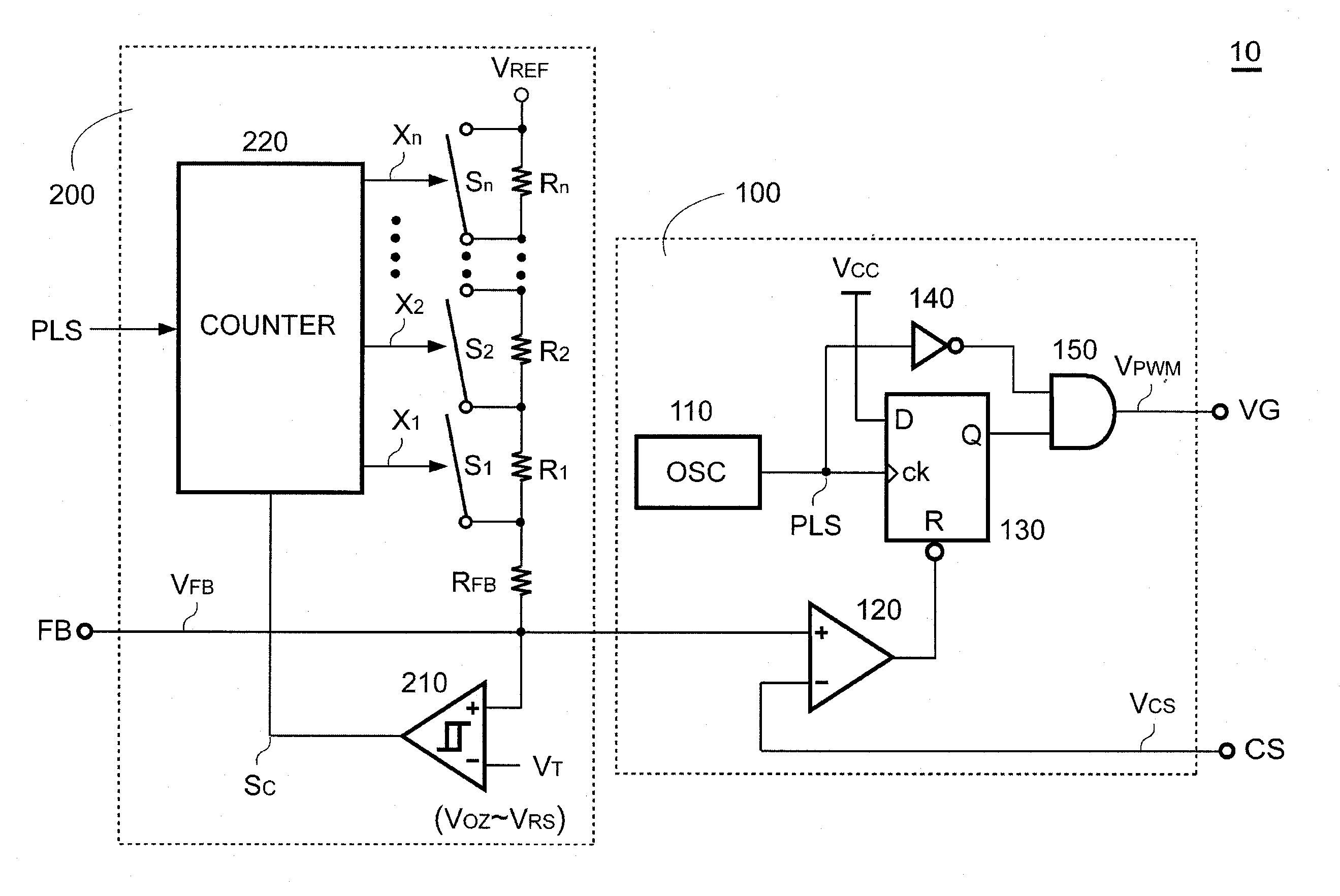
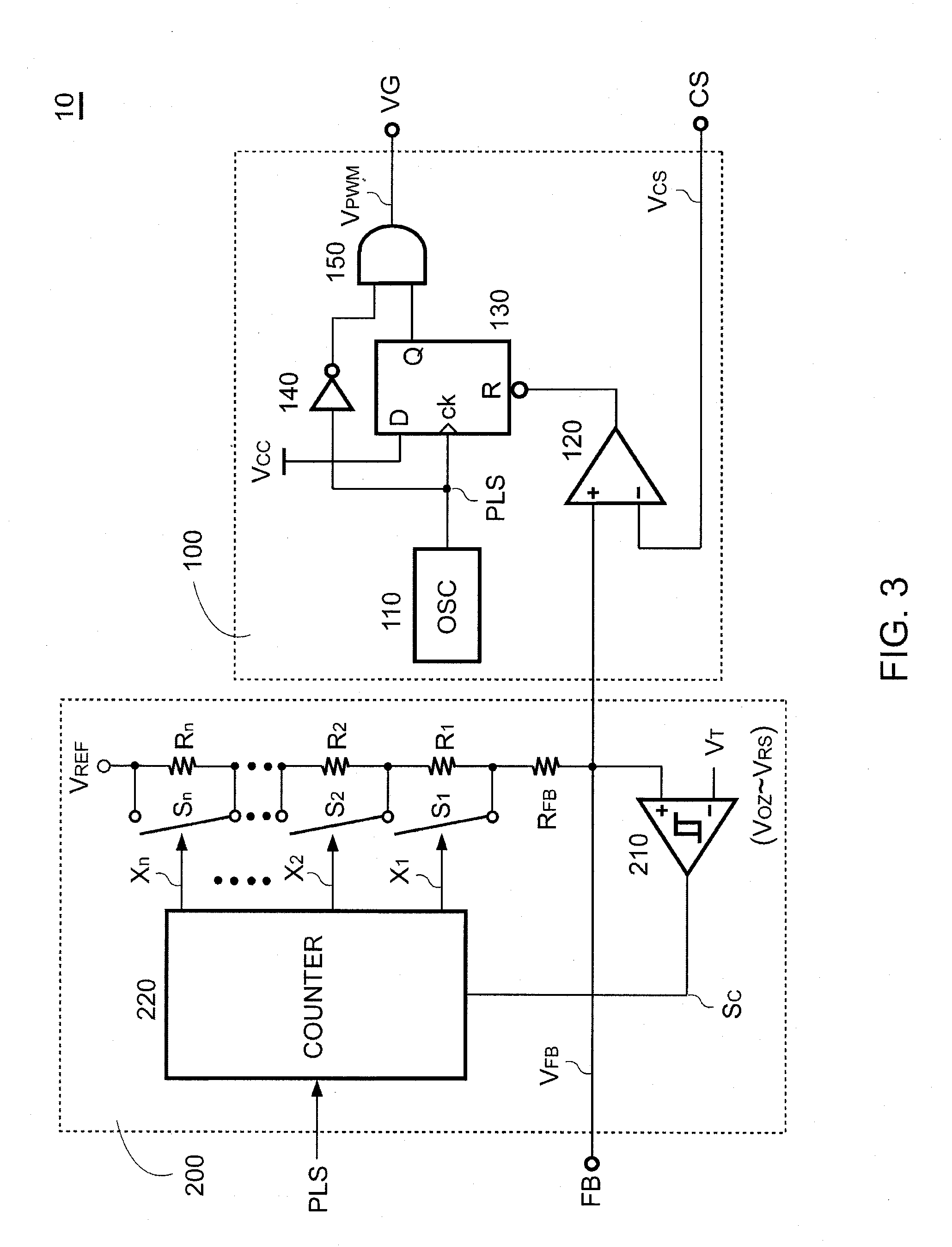
[0019]FIG. 3 shows a preferred embodiment of the control circuit 10 according to the present invention. The control circuit 10 includes a PWM circuit 100 and a feedback circuit 200. The PWM circuit 100 has mentioned above, so here is no need to describe again. The feedback circuit 200 includes a compare circuit 210, a counter 220 and a switching resistor circuit. The compare circuit 210 is implemented by a hysteresis comparator according to one embodiment of the present invention. A positive input of the compare circuit 210 coupled to the output of the power converter (shown in FIG. 1) receives the feedback signal VFB through the feedback terminal FB and the feedback l...


PUM


Abstract

A feedback circuit with feedback impedance modulation according to the present invention comprises a compare circuit, a counter and a switching resistor circuit. The compare circuit receives a feedback signal of a power converter to compare the feedback signal with a threshold signal for generating a control signal. The feedback signal is correlated to a load condition of the power converter. The counter is coupled to the compare circuit and generates a modulation signal in response to the control signal. The switching resistor circuit is coupled to the counter and a feedback loop of the power converter for modulating a feedback impedance of the power converter in response to the modulation signal. The feedback impedance is directly modulated from a lower resistance to a higher resistance when the load condition is reduced from a half/full-load to a no/light-load. The feedback impedance is gradually modulated from a higher resistance to a lower resistance when the load condition is increased from the no/light-load to the half/full-load.

Description

BACKGROUND OF THE INVENTION[0001]1. Field of the Invention[0002]The present invention relates to power converters, and, more specifically, the present invention relates to the control of switching mode power converters.[0003]2. Description of Related Art[0004]Switching power converters have been widely used to provide regulated voltage and current. Based on the restriction of environmental pollution, power converters have been strived to meet the power management and energy conservation requirements. FIG. 1 shows a circuit schematic of a conventional power converter. A control circuit 10 generates a switching signal VPWM to regulate an output of the power converter in response to a feedback signal VFB. The switching signal VPWM and the feedback signal VFB are generated at a drive terminal VG and a feedback terminal FB of the control circuit 10 respectively. The switching signal VPWM drives a power transistor Q1 coupled to a power transformer T1 for switching the power transformer T1...

Claims


Application Information

Patent Timeline
IPC IPC(8): H03H1/00
CPCH02M3/33507Y02B70/16H02M2001/0032Y02B70/10H02M1/0032
Inventor HUANG, WEI-HSUAN
Owner SEMICON COMPONENTS IND LLC
Why Eureka
Try Eureka