Directional multiple-polarization wide band antenna network

a technology of antenna network and directional multi-polarization, which is applied in the direction of polarised antenna unit combinations, individual energised antenna arrays, polarisation/directional diversity, etc., can solve the problems of high integration cost, crucial and limited antenna positioning choice, and makes technical implementation impossibl

Inactive Publication Date: 2011-06-09
THALES SA
View PDF5 Cites 5 Cited by
  • Summary
  • Abstract
  • Description
  • Claims
  • Application Information

AI Technical Summary

Benefits of technology

[0012]The present invention is used in the field of direction-finding antennas and makes it possible in a direction-finding context to process signals of various polarizations without interaction with the carrier through the use of suitable direction-finding processing operations. In practice, in certain installation

Problems solved by technology

One of the main problems encountered when integrating direction-finding antennas is the choice of the mechanical structure holding the individual antennas and the positioning of the complete antenna system on a carrier structure.
For example, in the case of naval direction-finding, the choice of the positioning of the antenna is crucial and limited because of the many onboard equipment items such as radars, communication transmitters, navigation system, etc.
The main drawbacks to direction-finding antenna systems consisting of vertically and horizontally polarized omnidirectional antennas are notably:that their performance levels de

Method used


Image

  • Directional multiple-polarization wide band antenna network
  • Directional multiple-polarization wide band antenna network
  • Directional multiple-polarization wide band antenna network

Examples


Embodiment Construction

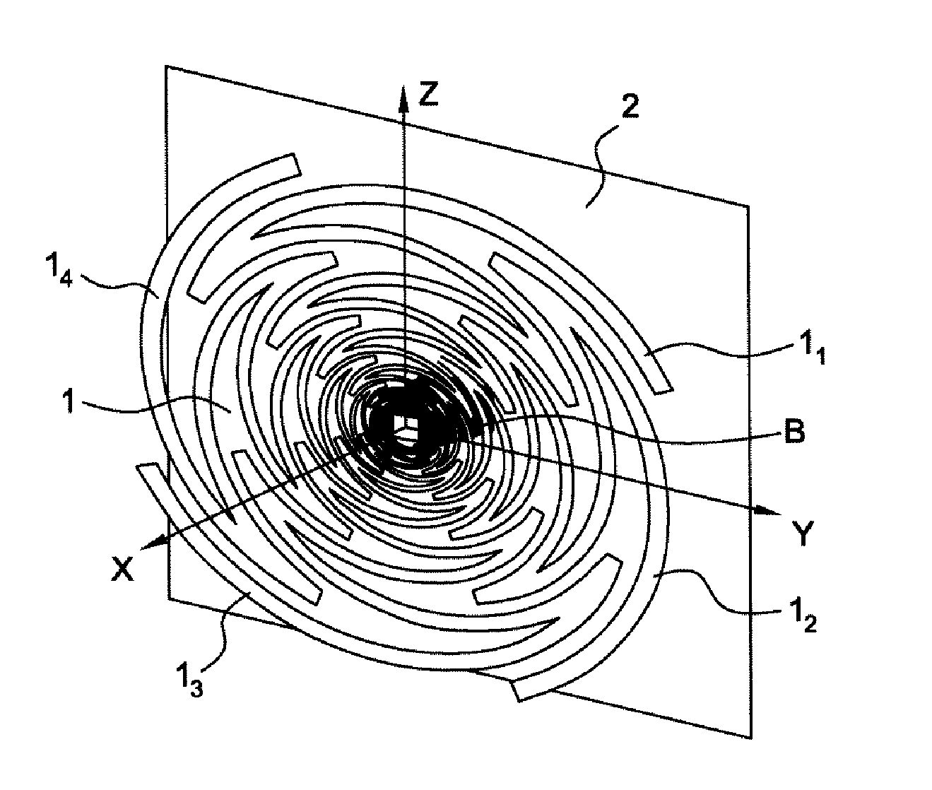
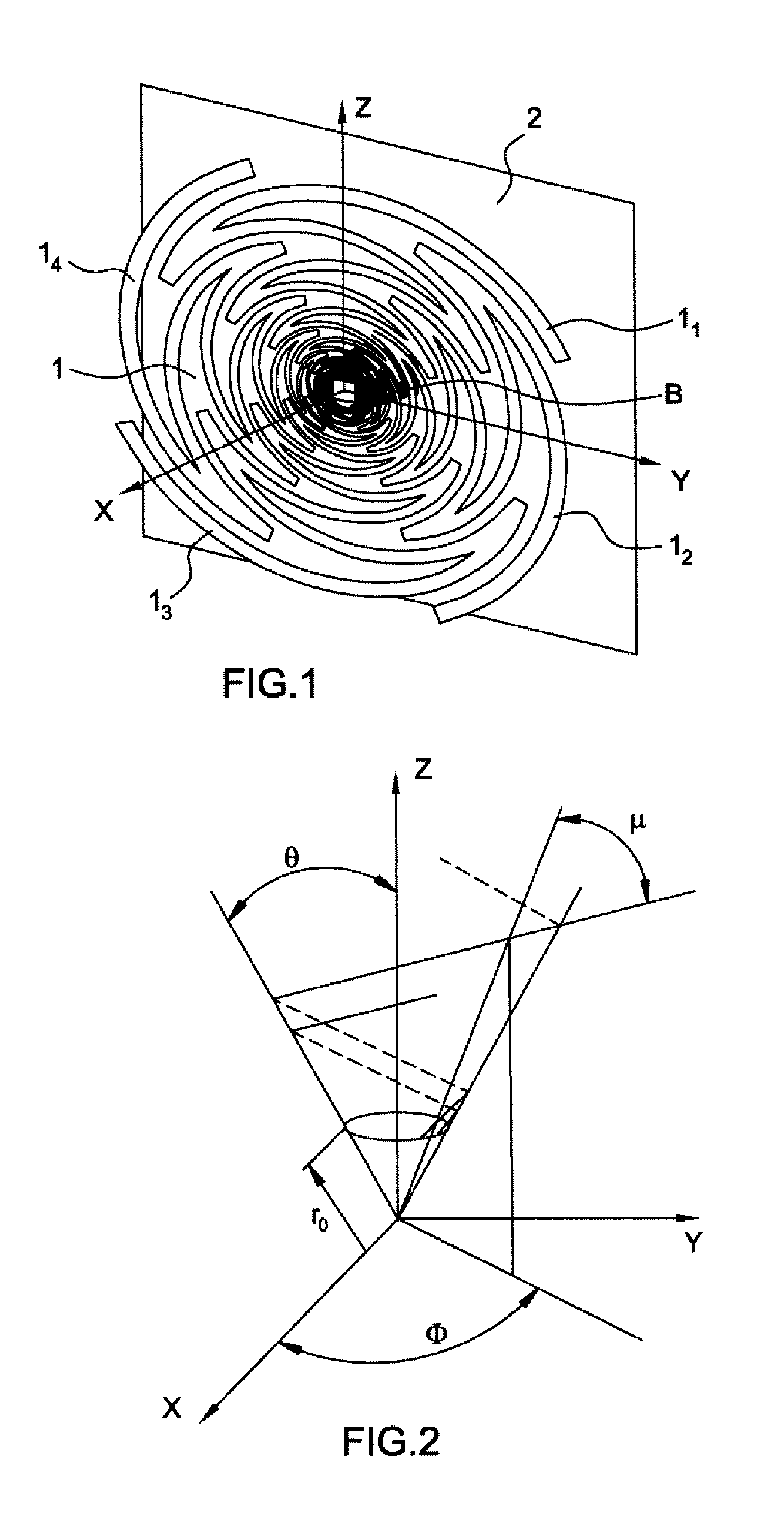
[0031]FIG. 1 represents an individual antenna 1 printed on a dielectric substrate including four complementary or self-complementary branches 11, 12, 13 and 14. This element 1 is arranged in front of a reflector 2 which notably makes it possible to make the antenna element 1 or individual antenna directional. The reflector 2 also has a protection function with respect to the spurious radiations originating from other antenna elements forming part of the array according to the invention. This reflecting plane notably makes it possible to obtain a better efficiency than when an absorbent cavity is used.

[0032]The geometry of an equi-angular spiral is defined by:

rk=r0exp(a(Φ-2πKN))

r denoting the radius of an arm of the spiral and r0 the radius at the center

where K represents the arm of the spiral concerned, N the number of arms and “a” the constant of the spiral with

a=sin(θ)tan(μ)

as defined in FIG. 2 in a polar coordinates diagram.

[0033]For a planar convoluted spiral,

θ=π / 2anda=1tan(μ)

Th...


PUM


Abstract

A directional multiple-polarization wide band antenna array working in a selected frequency band and including a plurality of N individual sensors of convoluted spiral type complementing a number of strands arranged according to a structure making it possible to obtain for obtaining a given azimuth coverage, each of the N sensors including a reflecting plane attached to the antenna by an insulating spacer E, matching cells suited to the working frequency band of said array, and separate output channels (5) and (7) for the vertically-polarized signals and for the horizontally-polarized signals. The antenna array also including a device suitable for executing a direction-finding algorithm that uses the amplitude and the phase of said signals and is matched to the configuration of the array.

Description

CROSS REFERENCE TO RELATED APPLICATIONS[0001]This is a U.S. National Phase Application under 35 U.S.C. §371 of International Application no. PCT / EP2008 / 068090, filed Dec. 19, 2008, and claims benefit of French Patent Application No. 07 09050, filed Dec. 21, 2007, both of which are incorporated herein.FIELD OF THE INVENTION[0002]The invention relates to an architecture for an array of multiple-polarization wide band antennas and specifically to an array related to a frequency range comprising the very high frequency VHF (from 30 MHz to 300 MHz), the ultra high frequency UHF (from 300 MHz to 3 GHz) and the SHF frequency band (from 3 GHz to 30 GHz).BACKGROUND OF THE INVENTION[0003]One of the main problems encountered when integrating direction-finding antennas is the choice of the mechanical structure holding the individual antennas and the positioning of the complete antenna system on a carrier structure. In practice, this placement is strategic because the antenna array must not be d...

Claims


Application Information

Patent Timeline
IPC IPC(8): H01Q21/24
CPCH01Q9/27H01Q21/28H01Q21/205
Inventor BELLION, ANTHONYLE MEINS, CYRILLE
Owner THALES SA
Why Eureka
Try Eureka