Image forming apparatus
a technology of forming apparatus and forming tube, which is applied in the direction of valve details, valve arrangement, printing, etc., can solve the problems of insufficient supply of ink for maintaining the discharge stability of ink, failure of ink supply to the recording head, and long tubes, etc., to achieve stable negative pressure, improve operation speed, and simplify the effect of configuration
- Summary
- Abstract
- Description
- Claims
- Application Information
AI Technical Summary
Benefits of technology
Problems solved by technology
Method used
Image
Examples
first embodiment
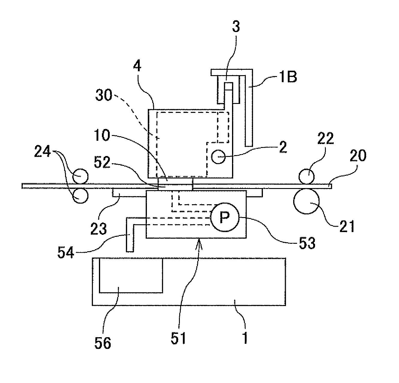
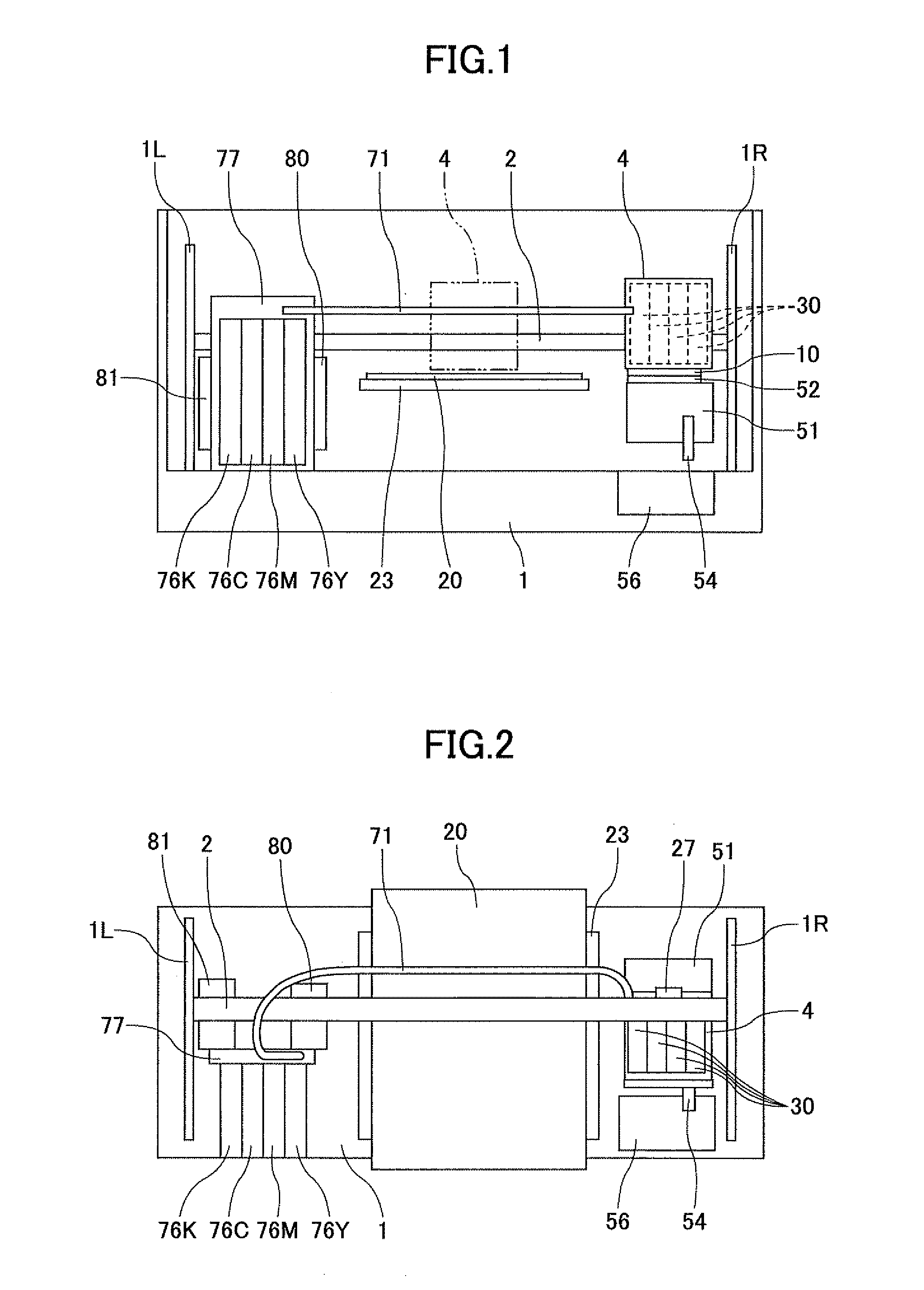
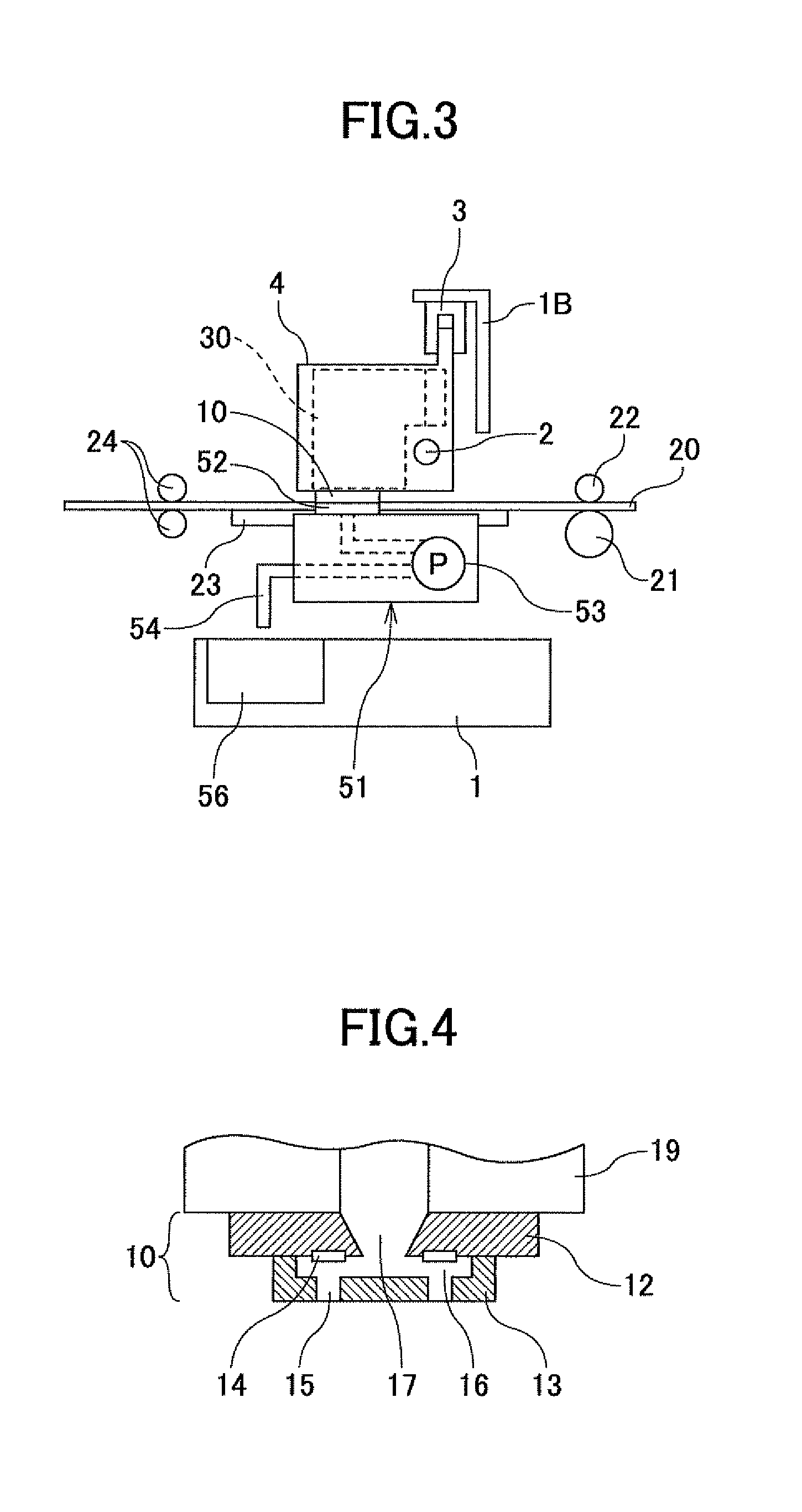
[0126]By doing this, the flow speed (flow rate) of ink in the liquid (ink) supply tube (first flow path) 71 is increased, and as illustrated in FIG. 16A, the valve body 88 of the flow path resistance varying units 83 is moved upward. In this case, the flow rate “Qv” when the valve body 88 is absorbed (moved upward) is much larger than the maximum discharge flow rate in normal printing operation. Therefore, the valve body 88 is moved upward to the highest possible position in its movable range. As a result, the valve body 88 seals the port 86a and a choke condition is established, so that the negative pressure in the cap member 52 is suddenly (further) increased. Namely, in this first embodiment of the present invention, the valve body top part 88t of the valve body 88 (first valve section) serves also as means (sealing member) for sealing (sealing unit) (disconnecting a fluid communication) between the liquid (ink) supply tube (first flow path) 71 and the second flow path 60 to seal...
second embodiment
[0141]Next, the recovery operation in the present invention is described.
[0142]In this second embodiment, a conical-shaped sealing rubber 68 is provided in the middle part on the upper surface of the valve body top part 88t of the flow path resistance varying unit 83 as a first elastic member which serves as a sealing member.
[0143]Similar to the first embodiment described above, when ink (liquid) is suctioned while the recording head 10 is covered with the cap member 52, the valve body 88 is moved upward and reaches the upper dead point as illustrated in FIG. 22A. In this condition, the sealing rubber 68 seals the port 86a on the liquid (ink) supply tube (first flow path) 71 side. Therefore, the liquid (ink) supply tube (first flow path) 71 is sealed and the choke condition is accordingly established.
[0144]Further, in this second embodiment, as illustrated in FIG. 22A, when the port 86a is sealed with the sealing rubber 68, a gap (space) 168 is formed (defined) surrounding the seali...
fourth embodiment
[0161]In this fourth embodiment, the choke condition is established under the condition that the ink inflow port (i.e., port 86c) from the pump (assist pump) 78 communicates with the recording head 10. Because of the feature, it may become possible to improve the efficiency of exhausting bubbles and foreign matter in the recording head 10 and the ink (liquid) supply path by increasing the exhaust amount of ink (liquid) when the pump (assist pump) 78 is driven (operated).
[0162]Further, in this fourth embodiment, a case is described where the sealing rubber 69 as the second elastic member (sealing member) has a circular shape. However, any other material having any other shape may be adequately selected and used such as an example where high-density foam is formed on the bottom surface or a lower circumference surface of the valve body 88.
[0163]Further, in the above descriptions, the operations and effects of the present invention are described based on an example where different colo...
PUM
 Abstract
Description
Claims
Application Information
 - R&D
- Intellectual Property
- Life Sciences
- Materials
- Tech Scout
- Unparalleled Data Quality
- Higher Quality Content
- 60% Fewer Hallucinations
Browse by: Latest US Patents, China's latest patents, Technical Efficacy Thesaurus, Application Domain, Technology Topic, Popular Technical Reports.
© 2025 PatSnap. All rights reserved.Legal|Privacy policy|Modern Slavery Act Transparency Statement|Sitemap|About US| Contact US: help@patsnap.com


