
Instrument and method for characterising an optical system

a technology of optical systems and instruments, applied in the direction of instruments, measuring devices, using optical means, etc., can solve the problems of inability to measure the focal length of the system to be characterized or the chromatic aberration value, the inability to measure the field curvature or the distortion of the objective, and the limited capacity of these instruments

Active Publication Date: 2011-06-09
IMAGINE OPTIC
View PDF9 Cites 3 Cited by
  • Summary
  • Abstract
  • Description
  • Claims
  • Application Information

AI Technical Summary

Benefits of technology

[0022]The beam coming from this secondary source passes through the system to be characterized and the wave front is analyzed on leaving the optical system. The diffuser is mounted on a translation stage making it possible to position it approximately at the point at which the beam is focussed by the optical system to be characterized on the “outward” path.
[0042]returning the illumination beam onto a pupil that is smaller than the pupil of the system to be characterized and off-axis. The fact of having a smaller pupil moreover makes it possible to have a greater depth of field on illumination (the source point formed on the diffuser remains small even when the diffuser is not perfectly in the focal plane of the objective),

Problems solved by technology

On the other hand, these systems do not generally give the measurement of the focal length of the system to be characterized or the chromatic aberration value, and are all limited, owing to their implementation, by numerical aperture.
Moreover, these systems measure only one field at a time and do not allow the measurement of the field curvature or the distortion of the objective.
However, the capacity of these instruments is limited by their inability to measure the optical aberrations of the system to be characterized (these instruments are not based on wave front measurement);other systems allowing measurement of the vignetting and the relative intensity as a function of the angle of view of an objective to be characterized but which do not provide the other data on the optical quality;andinstruments allowing the measurement of the distortion of an objective to be characterized but not providing the other data on the optical quality.

Method used


Image

  • Instrument and method for characterising an optical system
  • Instrument and method for characterising an optical system
  • Instrument and method for characterising an optical system

Examples


Embodiment Construction

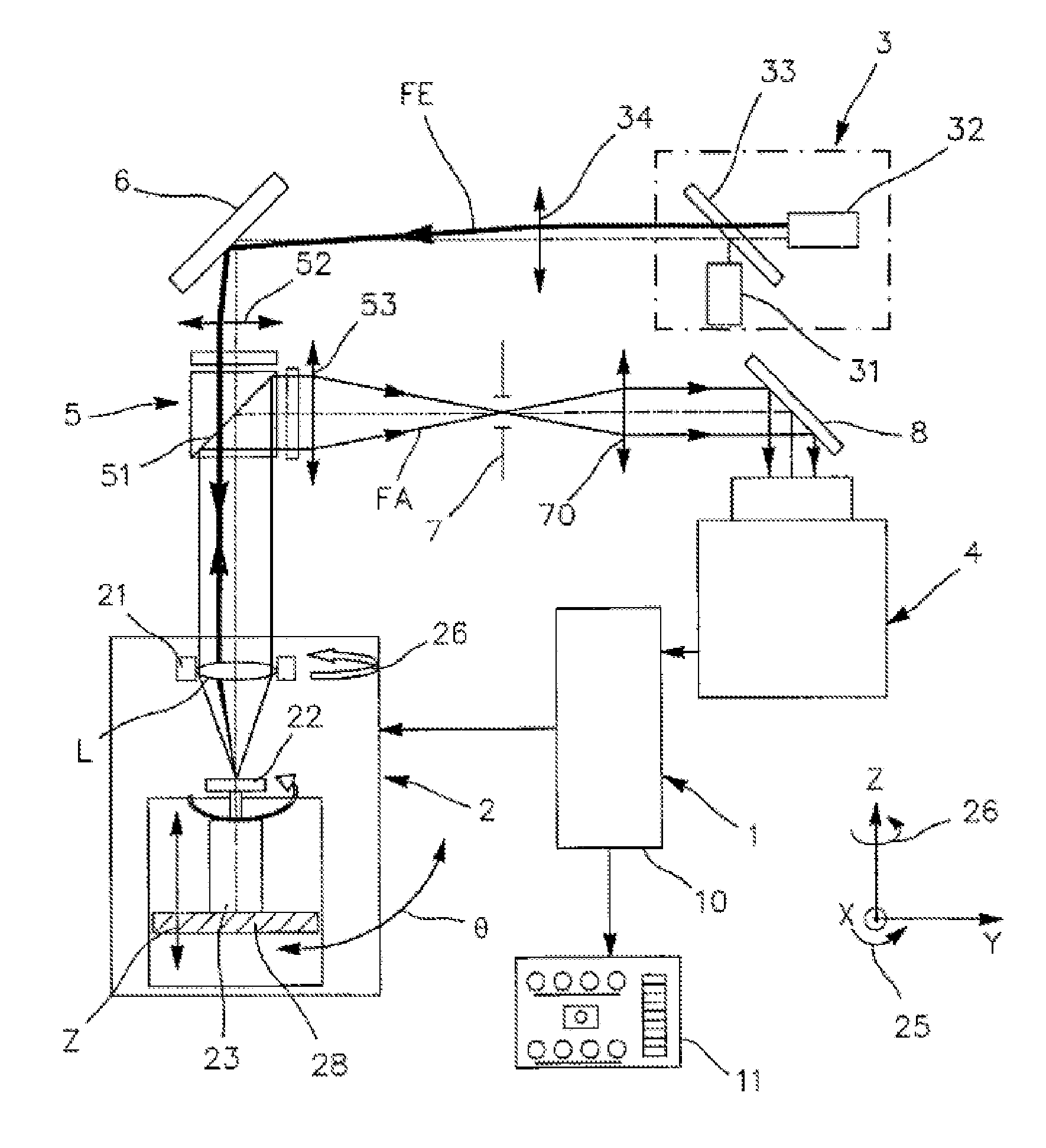
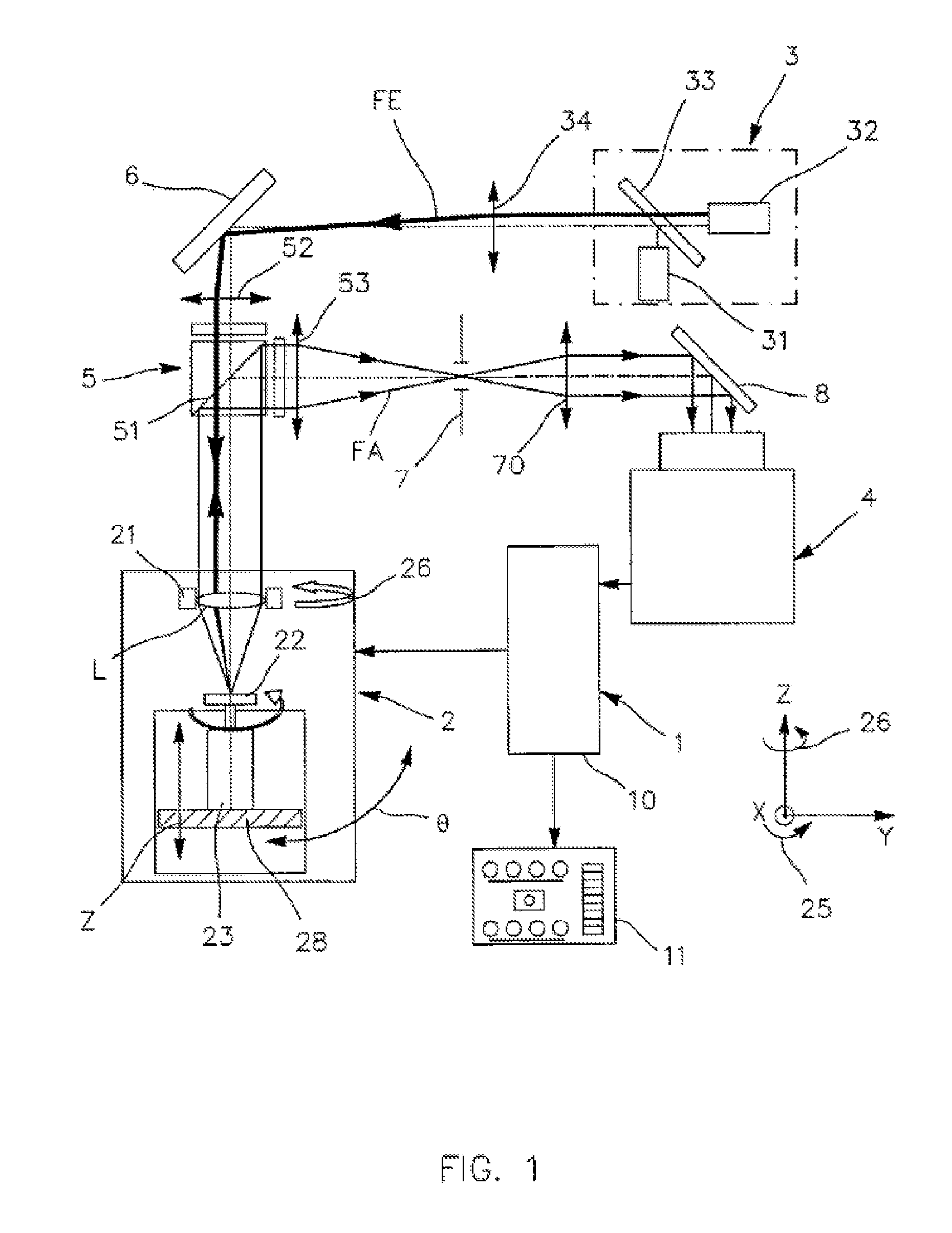
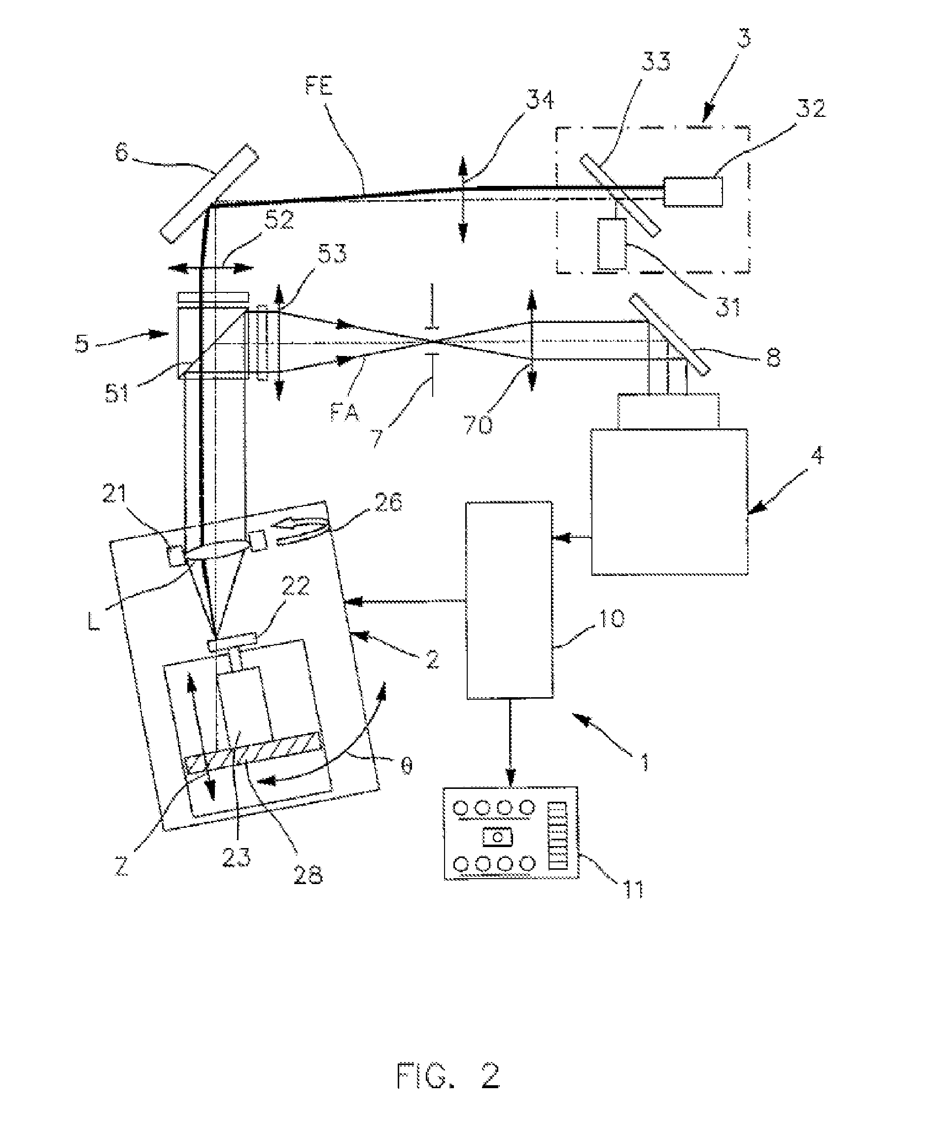
[0053]A characterization instrument 1 comprises, with reference to FIGS. 1 and 2, a system of illumination sources 3, a pivoting supporting structure 2 intended to receive on a mount 21 an optical system to be characterized, a beam separator module 5, a wave front analyzer module 4 and a processor module 10 provided in order to be connected to a terminal 11.

[0054]The illumination source system 3 includes a first source 31 at a first wavelength, a second source 32 at a second wavelength and a dichroic mirror 33. These two sources are produced for example in the form of laser diodes. The illumination beam FE produced is focussed by a lens 34 deflected by a mirror 6 through a lens 52 and the separator module 5 in order to reach an optical system L to be characterized, arranged in the mount 21 within the supporting structure 2.

[0055]This mount 21 receiving the optical system L can be firmly attached to the supporting structure 2 by magnetic coupling. A dedicated mechanism 29, for exampl...


PUM


Abstract

An instrument (1) for characterizing an optical system, includes: at least one primary source (3) for emitting an illumination light beam (FE); an optical device for directing the illumination beam (FE) onto the optical system (L) to be characterized; a wave front analyzer (4) adapted for receiving a beam from the optical system (L); and a unit for processing the measure signals from the wave front analyzer (4), adapted for providing characterization information of the optical system (L). The instrument further includes a scattering member (22) substantially provided in the focal plane of the optical system (L) so as to create a secondary source generating a secondary beam flowing through the optical system (L) and further directed towards the wave front analyzer.

Description

[0001]The present invention relates to an instrument for characterizing an optical system. It also relates to a characterization method implemented in this instrument.PRIOR ART[0002]There are already several instruments for characterizing an optical system. It is in fact possible to identify two families of instruments: systems based on measurement of the wave front (measurement of the aberrations) and other instruments that are not based on wave front measurement and do not allow the measurement of the optical aberrations of the system to be characterized.[0003]Phase measurement systems include:[0004]several phase measurement technologies: Fizeau interferometer, Hartmann or Shack Hartmann technology, lateral-shift interferometer technology;[0005]phase measurement systems making it possible to characterize the aberrations of a system. On the basis of this measurement it is generally possible to determine, in addition to the aberrations, the point spread function (PSF) and the modula...

Claims


Application Information

Patent Timeline
Patent Type & Authority Applications(United States)
IPC IPC(8): G01B9/00G01M11/02
CPCG01M11/0207G01M11/0285G01M11/0257
Inventor LEVECQ, XAVIERDOVILLAIRE, GUILLAUME
Owner IMAGINE OPTIC
Learn More