Low-voltage start up circuit and method for DC-DC boost converter

a low-voltage start-up circuit and boost converter technology, which is applied in the direction of dc-dc conversion, power supply lines, power conversion systems, etc., can solve the problems of over-design of power switches, no circuitry in the usual control circuitry inside the boost converter is operable during the start-up operation, and no circuitry in the boost converter is operable. , to achieve the effect of low power consumption and low complexity

Active Publication Date: 2011-06-09
TEXAS INSTR INC
View PDF6 Cites 24 Cited by
  • Summary
  • Abstract
  • Description
  • Claims
  • Application Information

AI Technical Summary

Benefits of technology

[0014]It is an object of the invention to provide a low-cost, low complexity, low power start up circuit and method for use

Problems solved by technology

Consequently, none of the circuitry in the boost converter is operable during the start-up operation.
However, until the output voltage of an energy harvesting device applied to provide the input voltage of a boost converter reaches a value of approximately 1.3 to 1.5 volts, none of the usual control circuitry inside the boost converter is operable.
However, that choice of duty cyc

Method used


Image

  • Low-voltage start up circuit and method for DC-DC boost converter
  • Low-voltage start up circuit and method for DC-DC boost converter
  • Low-voltage start up circuit and method for DC-DC boost converter

Examples


Embodiment Construction

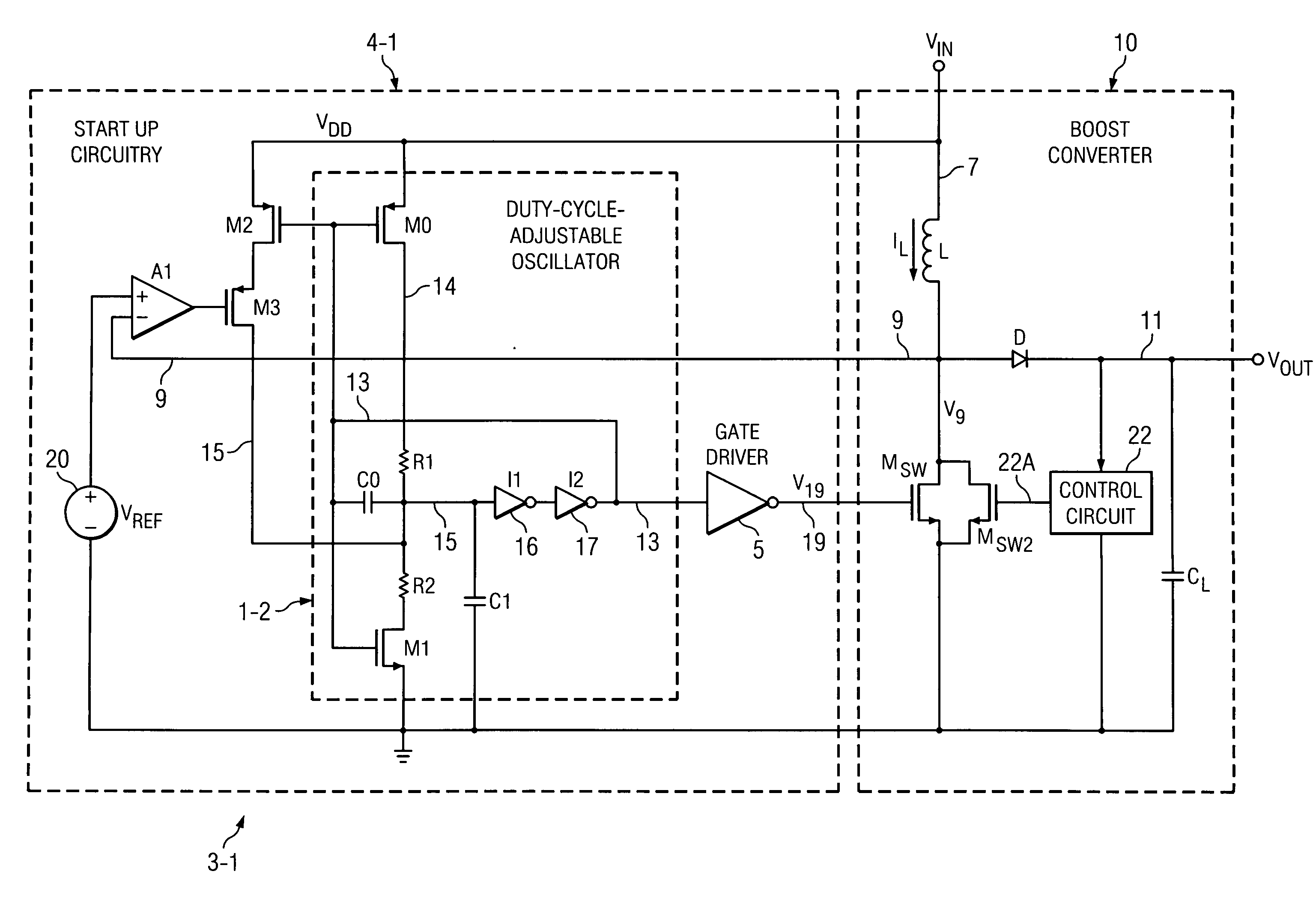
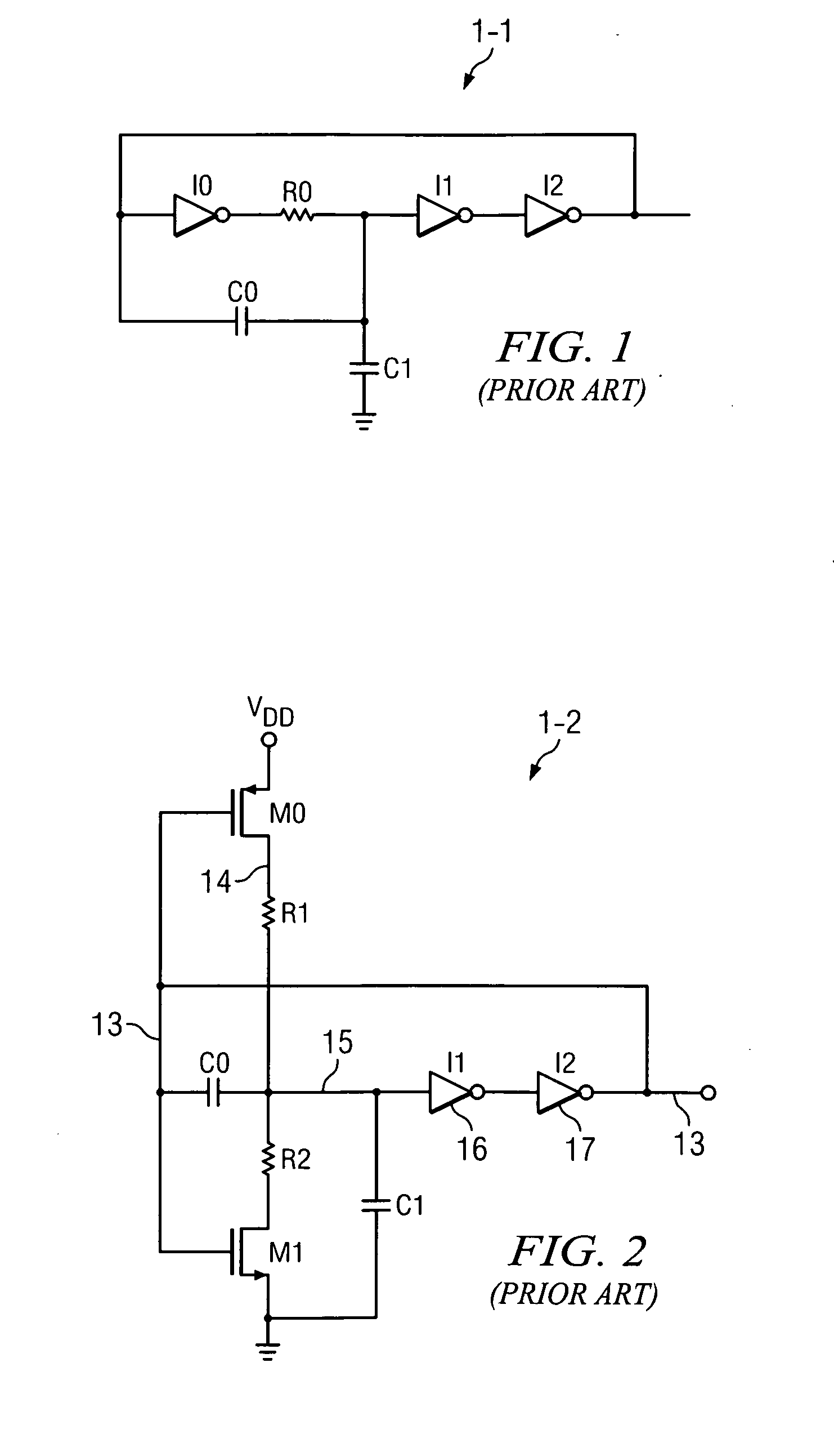
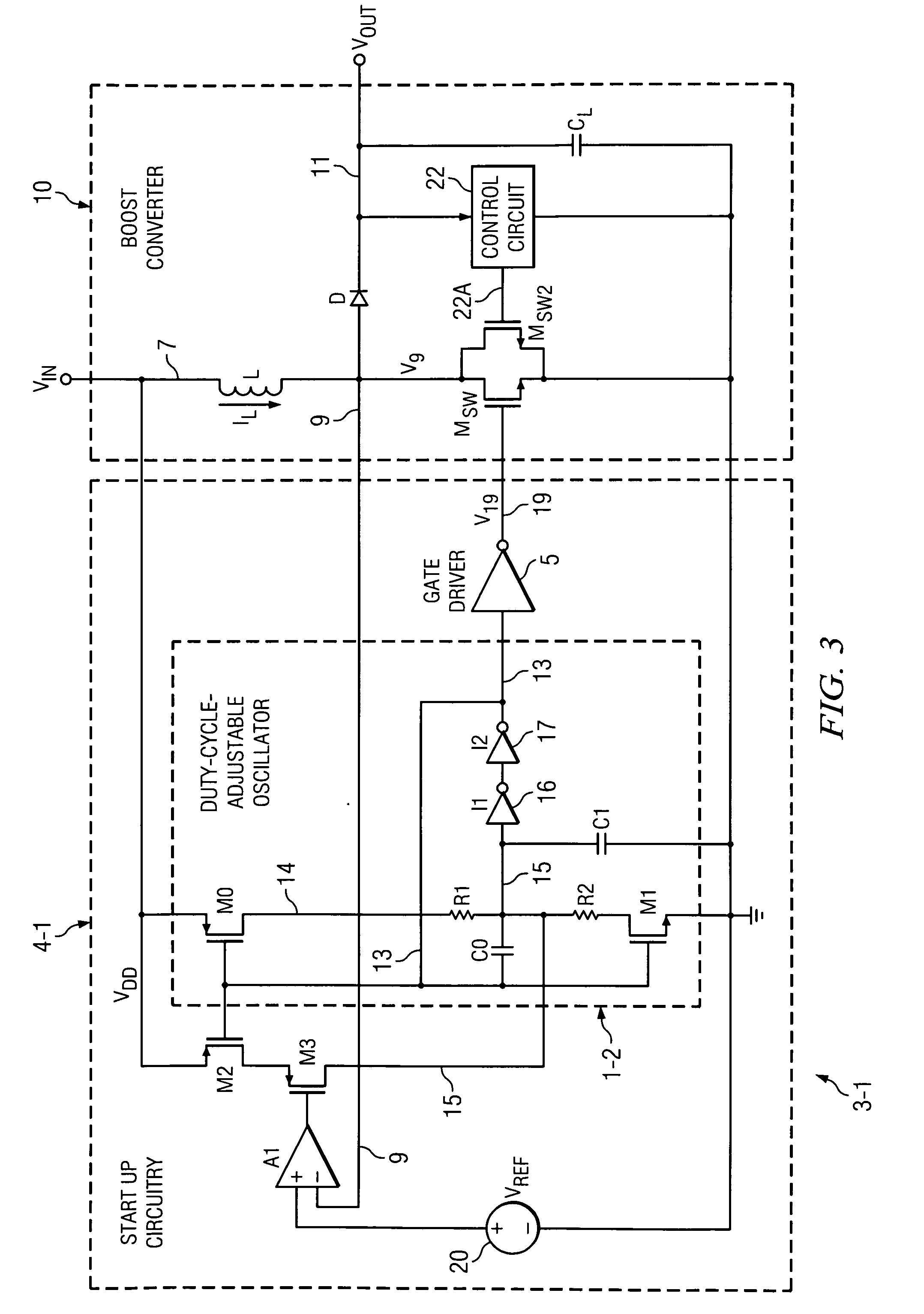
[0036]FIG. 3 shows a circuit 3-1 which includes a start up circuit 4-1 that includes the oscillator 1-2 of Prior Art FIG. 2, a conventional gate driver circuit 5, an amplifier A1, P-channel transistors M2 and M3, and a voltage reference circuit 20. The output 13 of oscillator 1-2 is connected to the input of gate driver circuit 5.

[0037]As in FIG. 2, the output 13 of oscillator 1-2 is connected to one plate of capacitor C0, the gate of a P-channel transistor M0, and the gate of a N-channel transistor M1. The other plate of capacitor C0 is connected by conductor 15 to the input of inverter I1 and one plate of capacitor C1, the other plate of which is connected to ground. The output of inverter I1 is connected to the input of inverter I2, the output of which is connected to conductor 13. The drain of transistor M0 is connected by resistor R1 to conductor 15, and the source of transistor M0 is connected to VDD. The drain of transistor M1 is connected to conductor 15 by resistor R2, and ...


PUM


Abstract

A start up circuit (4-1) for a boost circuit (10) includes an adjustable-duty-cycle oscillator (1-2) that turns on a switch transistor (MSW) connected to an inductor (L) receiving an input voltage (VIN). If a voltage (V9) of a junction between the transistor and the inductor exceeds a predetermined value corresponding to a maximum inductor current (IL), an amplifier (A1) immediately terminates a first phase of an oscillator cycle, which turns off the transistor. Built-up inductor current is steered into a load. Duty-cycle-adjustment circuitry (R1,R2,C1) causes the oscillator to complete a normal second phase of the cycle before a new cycle begins.

Description

BACKGROUND OF THE INVENTION[0001]The present invention relates generally to improving the operability of energy harvesting devices, and more particularly to low voltage start up circuitry for a boost converter in an inductive energy harvesting system.[0002]Engineers have attempted to design “ultra low” power integrated circuits, for example integrated circuits that require extremely low amounts of operating current and which can be operated without being plugged into conventional AC power systems. Instead, it is desirable that such ultra-low-power integrated circuits be powered by small amounts of power “scavenged” or “harvested” from ambient solar, vibrational, thermal, and / or biological energy sources by means of micro-energy “harvesting devices” and stored in batteries or super-capacitors.[0003]Prior Art FIG. 1 shows a conventional ring oscillator 1-1. Ring oscillator 1-1 has an oscillation frequency determined by the values of resistor R0 and capacitors C0 and C1. For a CMOS imp...

Claims


Application Information

Patent Timeline
IPC IPC(8): H02M1/36
CPCH02M3/156H02M1/36Y10S323/901
Inventor IVANOV, VADIM V.
Owner TEXAS INSTR INC
Why Eureka
Try Eureka