Detecting objects

a technology for objects and detection methods, applied in the field of objects detection, can solve the problems of inability to detect single cells, difficult if not impossible, and expensive automatic technologies,

Active Publication Date: 2011-06-09
OXFORD UNIV INNOVATION LTD
View PDF15 Cites 66 Cited by
  • Summary
  • Abstract
  • Description
  • Claims
  • Application Information

AI Technical Summary

Benefits of technology

Thus, embodiments of the invention can provide a cost effective, imaging modality suitable for observing live cell based assays. The system may use a small aperture light-emitting diode (LED) and a charged-coupled device (CCD) array in an arrangement comparable to that used by Lange et al. However the geometries are arranged in such a way that the diffraction patterns due to cells are directly recorded (as opposed to the shadow images recorded by Lange et al), offering a cell ‘signature’ amenable to automated detection. By varying the CCD-cell distance, the size of the diffraction pattern on the CCD can be controlled.

Problems solved by technology

At present all optical imaging of biological samples, with a few exceptions, is still undertaken on large expensive microscopes that obviously do not exploit many of the advantages offered by LOC devices, such as small size and low cost.
This method however, relies on the sample being moved across the sensor at a known velocity making the OFM unsuitable in situations where the cell / sample / object of interest remains fixed or moves at an unknown velocity, such as in clonogenic or chemotaxis type assays.
The resolution of the resultant image is inherently set by the pitch and pixel size of the video camera chip, making (in practice) the detection of single cells (e.g. mammalian cells with a diameter of =15 μm) extremely difficult if not impossible.
Also most cells are transparent at visible wavelengths and thus may not produce a discernable shadow.
Current technologies for monitoring live cells over time are largely reliant on manual intervention and expertise; automatic technologies are immature or bulky and expensive.
Automation of this process may be performed by the creation of an incubation chamber that surrounds the microscope, but keeping cells viable in this environment is usually more problematic.
This approach also requires the use of an expensive automated microscope.
Detection and tracking of the cells by processing the images from the phase-contrast microscope is also possible in principle, but is difficult in practice because of the large variability in the visual appearance of cells when visualized in this manner.

Method used


Image

  • Detecting objects
  • Detecting objects
  • Detecting objects

Examples


example 1

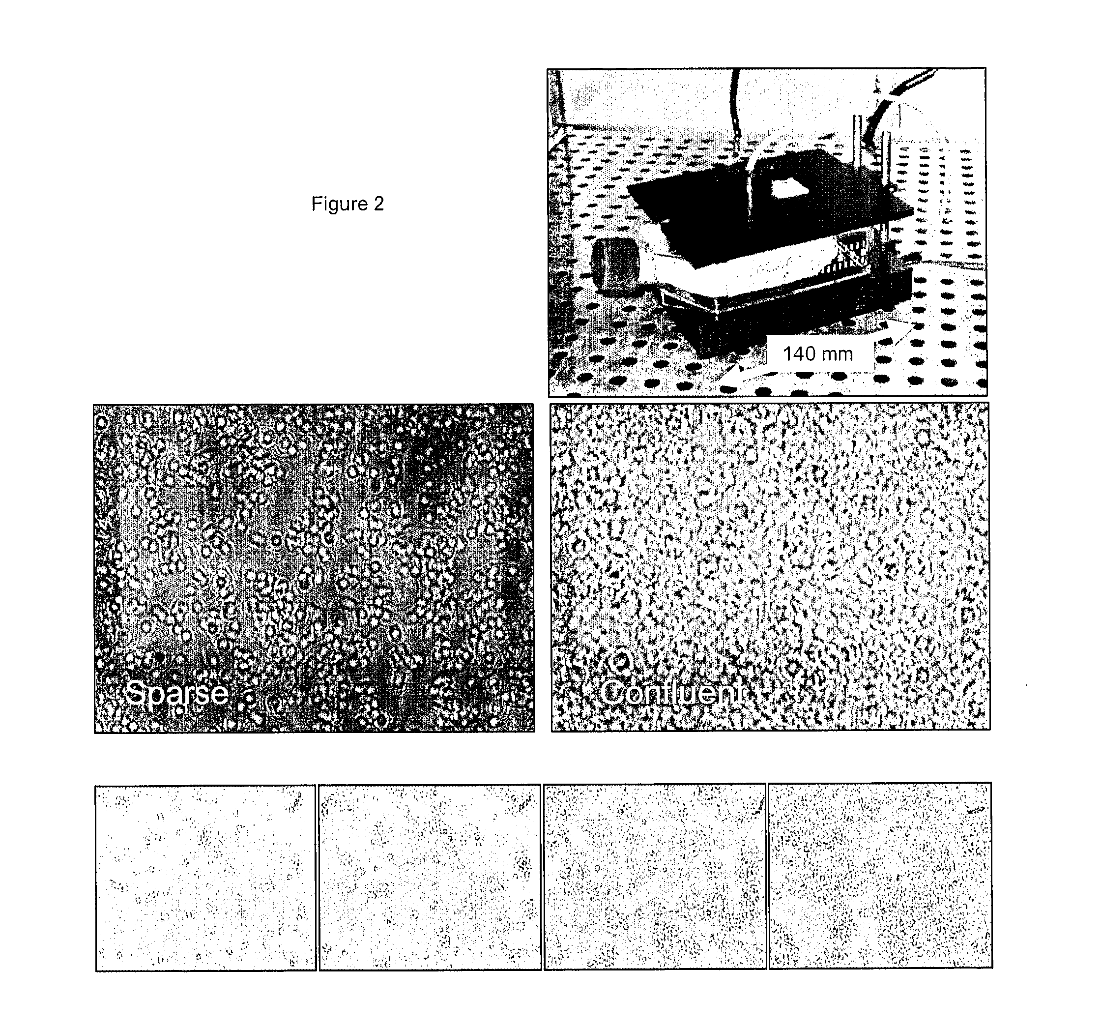
FIG. 2 shows an example of a CyMap apparatus used inside an incubator (top right image) and typical raw images of cells plated in a T75 flask (middle two images) showing a sparse and near-confluent cell culture. Standard cell preparation and cell growing techniques were used. The flask was imaged throughout the cell growth process, i.e. the flask was located within the CyMap and within the incubator throughout. Selected images at successive time points over a 4 day period, from a ‘movie’ sequence, are shown in the lower four panels.

example 2

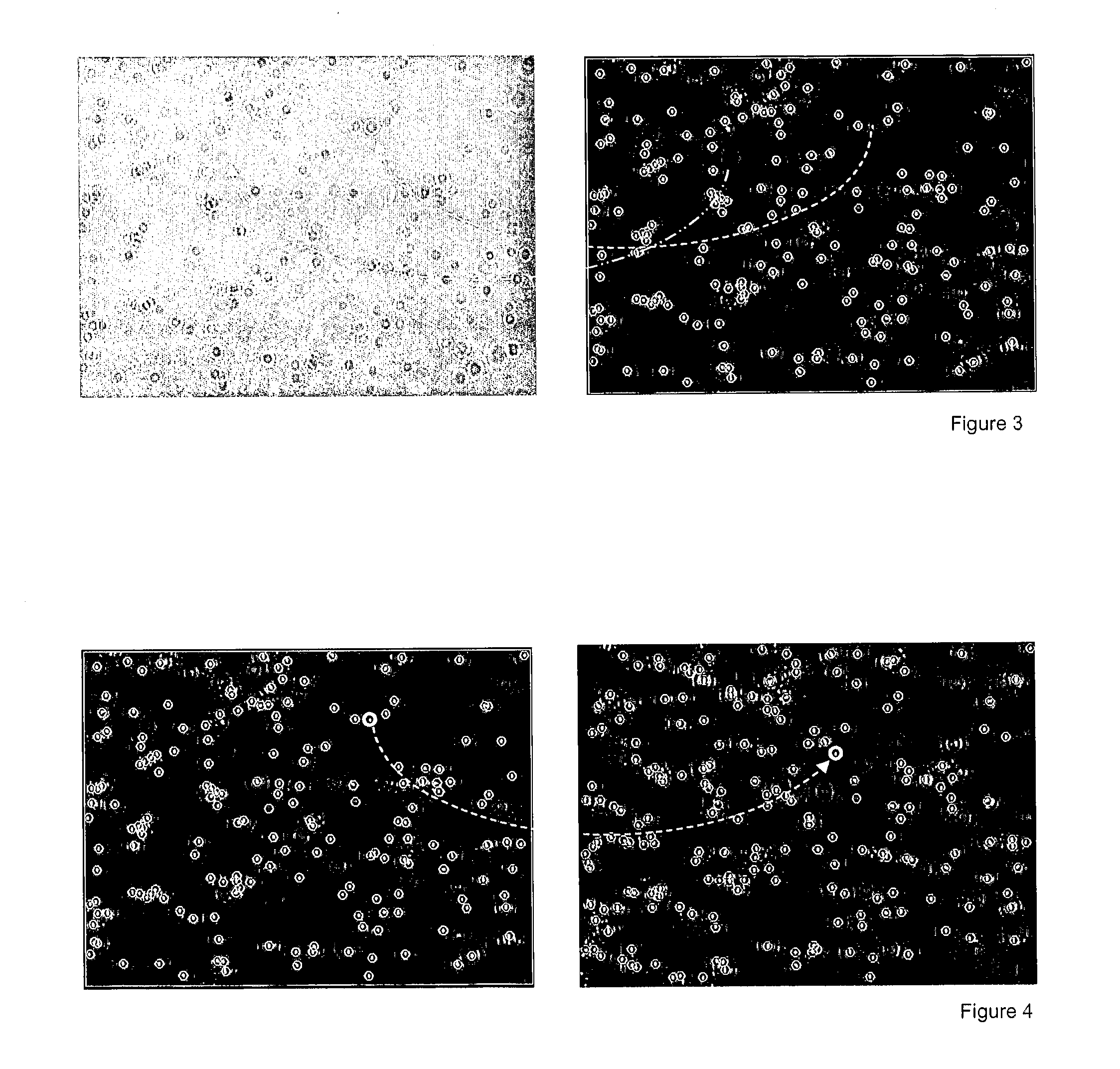
FIG. 3 shows ‘Raw’ CyMap image (left) and image-processed result (right). In this instance all attached cells have been ‘found’, one example cell is outlined with a white ring and its location mapped on the raw image (short-dashed line). Note that a ‘floating’ or unattached cell (long-dashed-dot line) is not identified and is rejected by the image-processing software;

example 3

FIG. 4 shows an example of cell coordinate tracking, showing results of image-processing data taken over approximately 24 hours, with a time-interval of 4 hours between the left and right images. The ‘movement’ of one individual is identified by the dashed line and associated white circles;


PUM

PropertyMeasurementUnit
diameteraaaaaaaaaa
diameteraaaaaaaaaa
timeaaaaaaaaaa

Abstract

The invention provides apparatus and methods for detecting objects in samples. The sample is held in the transmission path of light from a light source to a detector, whereby light from the light source interacts with objects in the sample. The patterns of light incident on the detector subsequent to its interaction with the objects are directly used to determine the presence of objects in the sample.

Description

FIELD OF THE INVENTIONThe present invention relates to apparatus and methods for detecting biological cells, other biological structures and / or other objects of interest. The apparatus and methods can be used, for instance, for mapping the positions of and / or tracking movements of the objects (e.g. cells). Embodiments of the invention are especially (although not necessarily exclusively) suited to mapping and / or tracking live cells, for example live mammalian cells. The apparatus and methods can be useful in automating a wide range of live cell-based assays and can be incorporated, for example, in lab-on-chip devices, microfluidic platforms or hand-held devices.BACKGROUNDThere have been significant advances in recent years in the development of microfluidic / lab-on-a-chip (LOC) cellular assays, with numerous papers detailing different detection / analysis methods which may be used in such devices [1-5]. However, these all tend to be interrogation methods which provide measurements of s...

Claims


Application Information

Patent Timeline
Patent Type & Authority Applications(United States)
IPC IPC(8): C12Q1/06C12M1/34C12Q1/02
CPCG01N15/1434G01N15/1456G03H2001/0825G03H2001/0447G03H2001/0033G03H2222/34G03H1/0443G03H1/0465G03H2222/52G03H2222/53G03H2222/24G03H1/0866G01N15/1436G01N21/4788G01N21/49G01N33/4833G01N2015/0065G01N2201/062G01N2201/12
Inventor VOJNOVIC, BORIVOJBARBER, PAUL RICHARDPOPE, IESTYNSMITH, PAUL JAMESERRINGTON, RACHEL JANE
Owner OXFORD UNIV INNOVATION LTD
Why Eureka
Try Eureka