Process-gas supply and processing system

a technology of processing system and process gas, which is applied in the direction of functional valve types, machines/engines, transportation and packaging, etc., can solve the problems of inefficiency of diluent gas, inability to make a diluted process gas of the desired density, and inability to precisely control the density of process gas, so as to reduce the cost of gas and reduce the cost of operation.

Inactive Publication Date: 2011-06-16
TOKYO ELECTRON LTD
View PDF14 Cites 330 Cited by
  • Summary
  • Abstract
  • Description
  • Claims
  • Application Information

AI Technical Summary

Benefits of technology

[0010]Taking the above problems into consideration, the present invention has been made so as to efficiently solve the same. The object of the present invention is to provide a process-gas supply system and a processing apparatus, which are capable of precisely controlling a density of a process gas at a significantly low density (concentration) ranging from a several ppb level to a several hundreds ppb level. Another object of the present invention is to reduce a cost of the process gas by a reuse thereof.

Problems solved by technology

As described above, when a process gas, which is flown at a slight flow rate, is diluted with a diluent gas of a large amount, it is considerably difficult to precisely control a density of the process gas at the aforementioned significantly low density ranging from a several ppb level to a several hundreds ppb level, because of properties of a flow rate controller such as a mass flow controller.
Further, unless an enormous amount of diluent gas is flown, it is impossible to make a diluted process gas of a desired density.
Thus, the use of the diluent gas is inefficient, which increases a cost of the gas.

Method used


Image

  • Process-gas supply and processing system
  • Process-gas supply and processing system
  • Process-gas supply and processing system

Examples


first embodiment

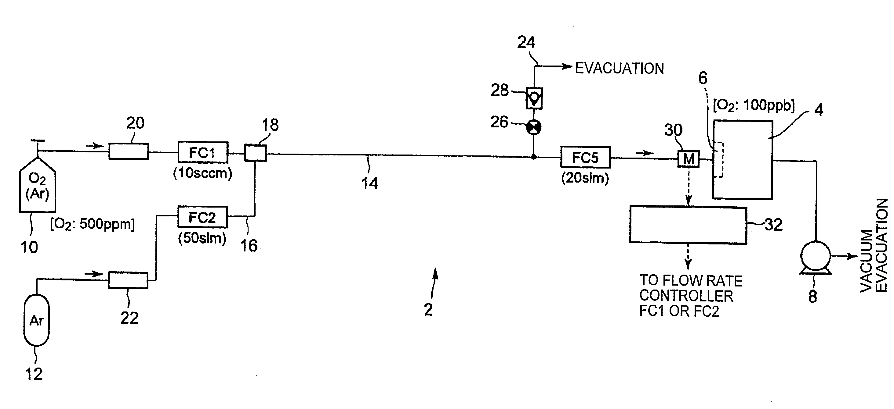
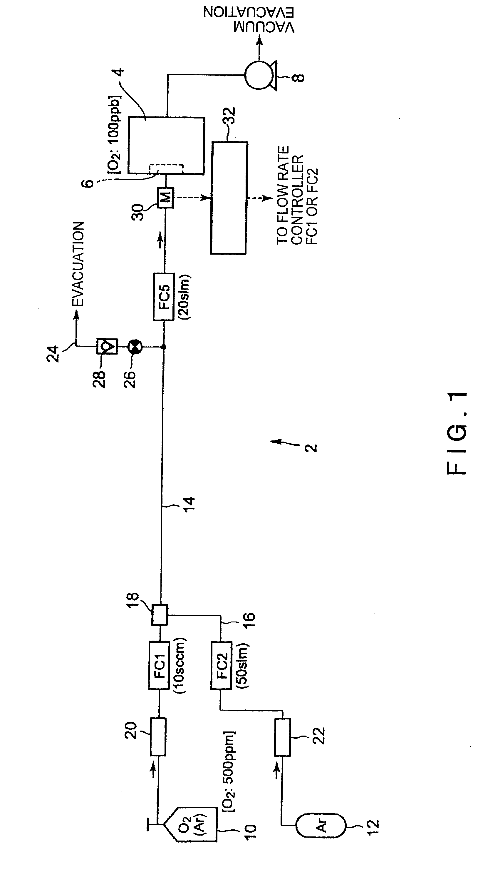
[0069]FIG. 1 is a structural view showing a first embodiment of a process-gas supply system according to the present invention, which is connected to a processing apparatus. As shown in FIG. 1, a processing apparatus 4 is used as a gas using system, as described above. A process-gas supply system 2 is connected to a gas introduction member 6 of the processing apparatus 4, in order to subject an object to be processed such as a semiconductor wafer, to various processes such as a film deposition process and an annealing process. An inside of the processing apparatus 4 is vacuumized by a vacuum pump 8 constituting an exhaust system (vacuum system), and thus is filled with a reduced pressure atmosphere.

[0070]The process-gas supply system 2 includes a process gas tank 10 that stores a process gas used in the processing apparatus 4, and a diluent gas tank 12 that stores a diluent gas for diluting the process gas. In this case, the process gas tank 10 and the diluent gas tank 12 may respec...

second embodiment

[0088]Next, a second embodiment of the process-gas supply system according to the present invention is described. FIG. 3 is a structural view showing the second embodiment of the process-gas supply system according to the present invention, which is connected to the processing apparatus 4. In FIG. 3, the same components as the components shown in FIGS. 1 and 2 are shown by the same reference numbers, and a detailed description thereof is omitted.

[0089]In the above first embodiment, there has been described the example in which the process gas tank 10 is filled with the gas which has been previously, precisely diluted with the diluent gas to a predetermined O2 density of 500 ppm, for example. On the other hand, in the second embodiment of the process-gas supply system, there is used, in place of the process gas tank 10 in the first embodiment, a process gas tank 34 which is filled with a pure O2 gas as a process gas. The pure process gas is diluted with a diluent gas in a stepwise ma...

third embodiment

[0096]Next, a third embodiment of the process-gas supply system according to the present invention is described. FIG. 4 is a structural view showing the third embodiment of the process-gas supply system according to the present invention, which is connected to the processing apparatus 4. In FIG. 4, the same components as the components shown in FIGS. 1 to 3 are shown by the same reference numbers, and a detailed description thereof is omitted.

[0097]In the above second embodiment, all the surplus gas discharged from the surplus-gas discharge ducts 24 and 40 is discarded. Meanwhile, in the third embodiment, a part of the surplus gas discharged outside the system is reused. To be specific, the surplus gas having a lower O2 density, i.e., the surplus gas discharged from the surplus discharge duct 24 on the downstream side can be reused. Thus, as shown in FIG. 4, in this embodiment, the surplus-gas discharge duct 24 on the downstream side is connected to a reusable gas duct 46. A distal ...


PUM

PropertyMeasurementUnit
pressureaaaaaaaaaa
steam pressureaaaaaaaaaa
temperatureaaaaaaaaaa

Abstract

A process-gas supply system 2 supplies a process gas diluted with a diluent gas to a gas using system 4. The process-gas supply system 2 includes a process gas tank 10, a diluent gas tank 12, a main gas duct 14 connecting the process gas tank 10 and the gas using system 4, and a diluent gas duct connecting the diluent gas tank 12 to the main gas duct. The respective main gas duct 14 and the diluent gas duct are provided with flow rate controllers FC1, FC2, and FC5. The diluent gas duct is connected to the main gas duct at a position on an immediately downstream side of one of a plurality of flow rate controllers other than the flow rate controller on the most downstream side. There is further provided a surplus-gas discharge duct 24 through which a surplus diluted process gas is discharged, the surplus-gas discharge duct 24 being connected to the main gas duct at a position on an immediately upstream side of one the flow rate controllers other than the flow rate controller on the most upstream side.

Description

FIELD OF THE INVENTION[0001]The present invention relates to a processing apparatus configured to subject an object to be processed, such as a semiconductor wafer, to a predetermined process, such as an annealing process and a film deposition process, and a process-gas supply system used therefor. In particular, the present invention relates to a process-gas supply system and a processing apparatus capable of precisely diluting a process gas with a diluent gas, at a significantly high dilution ratio, such as a ratio ranging from a several ppb level to a several hundreds ppb level, and of supplying the diluted process gas.BACKGROUND ART[0002]In general, when a semiconductor device is manufactured, a semiconductor wafer is generally subjected to various processes such as a film deposition process, an etching process, an annealing process, an oxidation and diffusion process, a modification process, and so on, repeatedly, so that a desired device is manufactured. Recently, in view of th...

Claims


Application Information

Patent Timeline
Patent Type & Authority Applications(United States)
IPC IPC(8): F16K15/00
CPCC23C16/45561C23C16/448Y10T137/7837Y10T137/8593G05D11/132
Inventor MATSUMOTO, KENJIITOH, HITOSHI
Owner TOKYO ELECTRON LTD
Why Eureka
Try Eureka