System for dissipating a lightning current generated by a thunderstorm discharge on an aircraft

a technology of thunderstorm discharge and lightning current, which is applied in the direction of aircraft lighting protectors, emergency protective arrangement details, and arrangements responsive to excess voltage, etc., can solve the problem that the principle of metalization of avionic equipment items on a metal skin cannot be applied to an airplane made of composite materials, and the aircraft structure is heavy. problem, to achieve the effect of dissipating the electric curren

Inactive Publication Date: 2011-06-16
AIRBUS OPERATIONS (SAS)
View PDF30 Cites 17 Cited by
  • Summary
  • Abstract
  • Description
  • Claims
  • Application Information

AI Technical Summary

Benefits of technology

[0032]The invention precisely has as an object to propose a dissipating system for an aircraft made of composite material which makes it possible to dissipate the electric current generated by lightning in the expanded metal layer.

Problems solved by technology

Aircraft with metal structure, however, have the drawback of being heavy, since the entirety of the structure is metal, with metal panels at least partially superposed in order to allow their assembly with metal joinings, which constitutes metal, therefore heavy, allowances.
With a structure made of composite material, however, metalization of the avionic equipment items is not ensured by the skin itself.
In fact, it is clearly understood that the principle of metalization of avionic equipment items on a metal skin cannot be applied on an airplane made of composite material since the skin made of composite material is not electrically conductive.
Now, this plane-on-plane contact entails drawbacks.
The result is an unreliable contact and a risk of corrosion that may hinder electric passage and lead to degradation of the protection against lightning.
This risk is high for the following reasons:it is difficult to guarantee a durable sealing between the electronic equipment items and the skin as a result of the curvature of the fuselage;over large surfaces, difficulties exist for controlling the galvanic element between the materials (in particular aluminum and carbon).
In fact, the treatment of this galvanic element requires insulating elements or semi-conductors to ensure sealing, which are incompatible with the requirements for protection against the direct effects of lightning, namely a minimal metal / metal surface contact of 400 mm2 and an electric resistance of 5 milliohms between the equipment item and the layer of expanded metal.
The risks then would be, on the one hand, of damaging the equipment item and, on the other hand, of damaging the electric or electromechanical equipment items connected to the ends of the electric cables.
The structure of FIG. 2 also has the drawback of not being able to reuse the equipment items of the preceding programs.
In fact, the avionic equipment items described for a metal airplane cannot be reused on a composite fuselage because the metalization device is modified.
Still another drawback relates to maintenance in cost and in repair time.
In fact, the repair of the lightning protection between the electronic equipment item and the structure of the aircraft requires dismantling of the equipment, which entails a considerable repair time and therefore a considerable down-time cost.

Method used


Image

  • System for dissipating a lightning current generated by a thunderstorm discharge on an aircraft
  • System for dissipating a lightning current generated by a thunderstorm discharge on an aircraft
  • System for dissipating a lightning current generated by a thunderstorm discharge on an aircraft

Examples


first embodiment

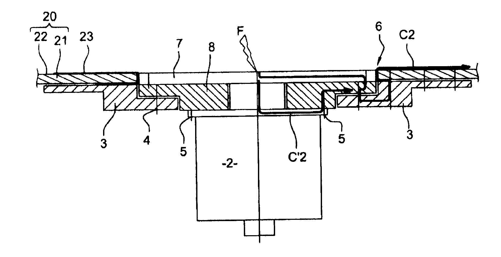
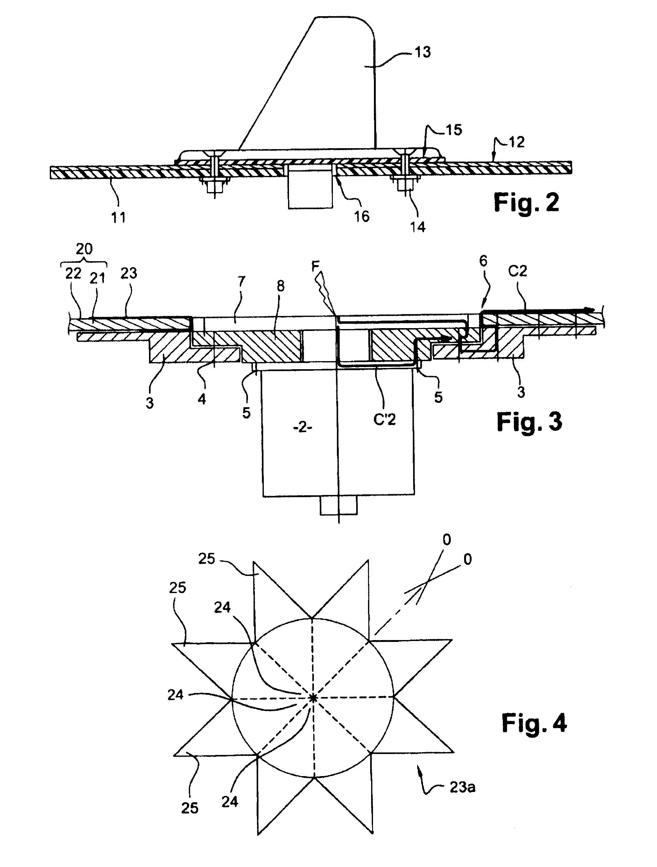
[0064]To produce the dissipating system according to this first embodiment, airplane-skin 20 made of composite materials according to standard techniques is drilled with an orifice 6 in order to allow passage of sensor 2. A pre-impregnated expanded metal plate is positioned around orifice 6 then applied on the walls of the said orifice then underneath the orifice. In this way the expanded metal plate covers the outside surface of the airplane-skin and its inside surface. A heating mat brought to approximately 180° C. then is installed on this expanded metal plate to ensure polymerization thereof.

[0065]In more detailed manner, a sanding operation may be performed prior to installing expanded metal plate 23, so as to achieve the metal mesh of the layer of expanded metal 22.

[0066]In this way expanded metal plate 23 is in surface contact with the layer of expanded metal 22 of the airplane skin. Expanded metal plate 23 also is in surface contact, inside the aircraft, with doubler 3.

[0067...

second embodiment

[0083]In the invention, the metal plate is made of an expanded metal ring and a ring-shaped plate made of titanium or copper. An example of this embodiment is shown on FIG. 6.

[0084]As in the first embodiment, airplane-skin 20 first is manufactured, then drilled with an orifice 6.

[0085]In this second embodiment, an expanded metal ring 30, pre-impregnated, then is installed around orifice 6, on the outside surface of airplane-skin 20. A heating mat then is placed on this ring 30 to ensure its polymerization.

[0086]A ring-shaped plate 31, made of titanium or of copper, then is placed in contact with expanded metal ring 30. The embodiment with a plate made of titanium will be described subsequently, its being understood that plate 31 also may be made of copper. This titanium plate 31 is installed above the central section of expanded metal ring 30. An exemplary assembly of the metal plate according to this second embodiment is shown on FIG. 7. This assembly comprises a first ring 30 made...

third embodiment

[0094]In the dissipating system of the invention, the metal plate is cast with the airplane-skin. This embodiment is shown on FIGS. 8 and 9. In this embodiment, airplane-skin 20 is not drilled in its thickness. The joggle of the skin provided for accommodating the ring-shaped plate made of titanium is implemented during the laying of the airplane-skin in the production mold. The tool then is a female mold.

[0095]As shown on FIG. 8, a ring-shaped plate made of titanium 34 is positioned around orifice 6, directly in airplane-skin 20. This plate made of titanium 34 was cast beforehand with airplane-skin 20 so that the airplane skin has a form adapted to the contour of the plate made of titanium 34.

[0096]An exemplary female mold in which the airplane-skin may be produced has been shown on FIG. 9A. This female mold incorporates the plate made of titanium 34. Once the plate made of titanium has been positioned in mold 35, the carbon folds are positioned inside the mold so that these carbon...


PUM


Abstract

A system for dissipating a lightning current produced by a thunderstorm discharge on an avionic equipment installed on the external skin of an aircraft, the external skin being made of a composite material covered with a layer of expanded metal and including an orifice in which there is positioned an aerodynamic plate covering the avionic equipment. The aerodynamic plate is attached to the external skin by a doubler. The system includes at least one metal plate at least partially surrounding the aerodynamic plate and mounted so as to ensure electrical continuity between the doubler and the layer of expanded metal so as to dissipate the lightning current into the layer of expanded metal.

Description

FIELD OF THE INVENTION[0001]The invention relates to a system for dissipating a lightning current produced by a thunderstorm discharge on an aircraft made of composite material. The invention also relates to a method for installation of this dissipating system.[0002]The invention finds applications in the field of aeronautics and, in particular, in the field of protection of aircraft and equipment items installed on the skin of the aircraft.STATE OF THE ART[0003]Usually, the structure of an aircraft (fuselage, nose cone, wing group, etc.) is made from metal panels mounted and fastened around an inner structure also metal. These metal panels are assembled with fastenings likewise metal and, once assembled, form the outer skin of the aircraft, also called airplane skin.[0004]On this outer skin, there generally are installed avionic equipment items, also called electronic equipment items, such as anemometric sensors, icing-condition detectors, radio antennas, navigation antennas, signa...

Claims


Application Information

Patent Timeline
Patent Type & Authority Applications(United States)
IPC IPC(8): H02H3/22
CPCB64D45/02
Inventor LE LOUARN, AMELIELABAL, FREDERIC
Owner AIRBUS OPERATIONS (SAS)
Why Eureka
Try Eureka