
Electronic device, integrated circuit and method for selecting of an optimal sampling clock phase

Active Publication Date: 2011-06-16
NXP USA INC
View PDF15 Cites 8 Cited by
  • Summary
  • Abstract
  • Description
  • Claims
  • Application Information

AI Technical Summary

Problems solved by technology

Consequently, the uplink controller does not have the knowledge about the correct clock phase to be used for extracting the data.
These over-sampling techniques are known to require very fast clock rates, whereby many functions significantly affect the fine margins in ensuring the correct clock signal is applied to the correct logic element at the correct time instant.
In such a situation, it is very difficult to ensure correct operation of sample and hold circuits, such as flip-flops, registers, etc., that is to ensure the correct data signal is input to the sample and hold circuit when the correct clock phase trigger is applied, particularly when high speed data is to be supported.
For example, known limitations with digital circuit design further encompass accommodating sampling techniques to operate across multiple data rates and clock rates (or clock phases being used), thereby increasing the complexity of the clock tree design.

Method used


Image

  • Electronic device, integrated circuit and method for selecting of an optimal sampling clock phase
  • Electronic device, integrated circuit and method for selecting of an optimal sampling clock phase
  • Electronic device, integrated circuit and method for selecting of an optimal sampling clock phase

Examples


Embodiment Construction

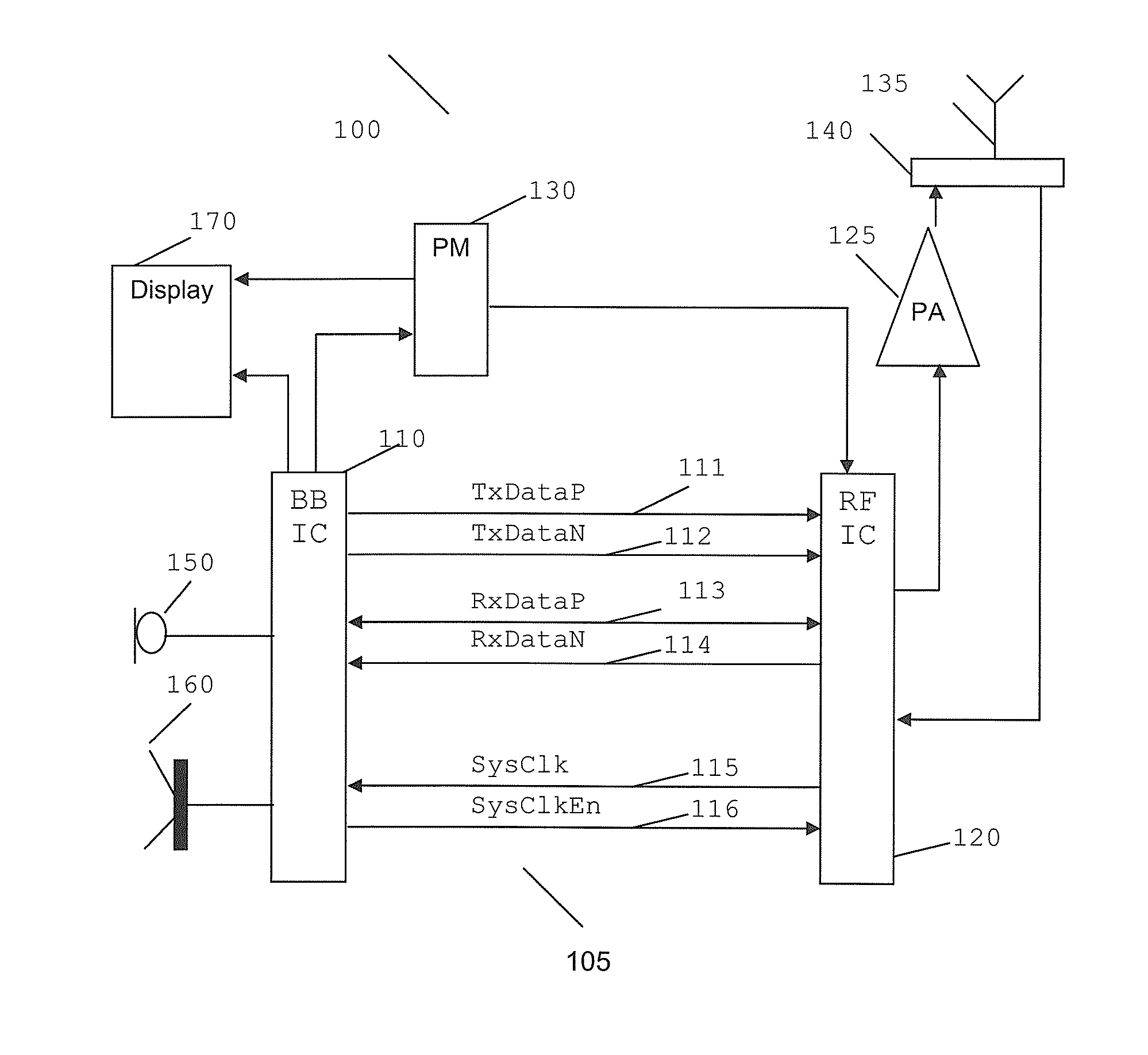
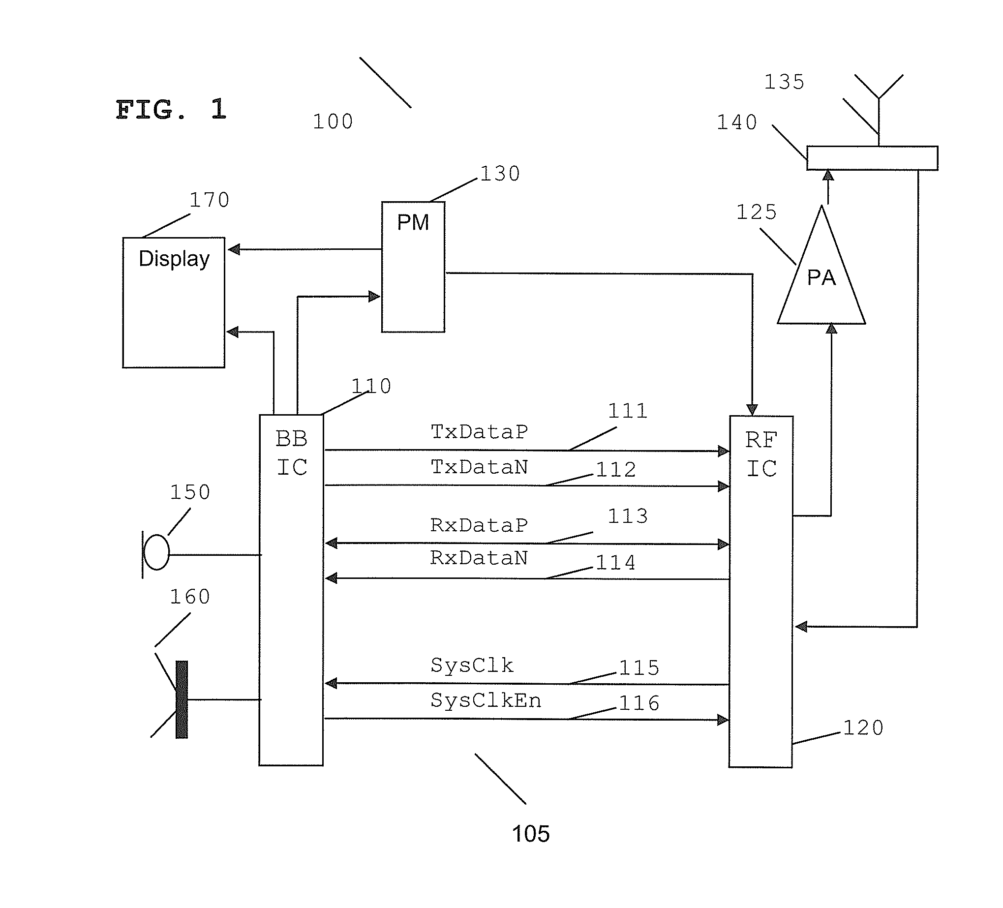
[0023]Embodiments of the invention will be described in terms of a wireless communication device, such as a multimode 3G mobile telephone. However, it will be appreciated that the invention may be embodied in any other type of electronic device, such as any wireless communication device, or even non-wireless communication device such as a computer-based device, which incorporates a data interface between respective sub-systems within the device. In the sense of a wireless application, it is envisaged that the inventive concept is applicable to any multimode wireless communication device, for example a wireless communication device supporting Bluetooth™ or ultra wideband orthogonal frequency division multiplex (UWB OFDM) technology or a multimode communication system combining 3G with variants of second generation (2x.G) technology or a future multimode communication system combining 3G with fourth generation (4G) technology.

[0024]In summary, the proposed technique to alleviate one o...


PUM


Abstract

An electronic device comprises a number of sub-systems coupled via an interface. One of the number of sub-systems comprises logic for receiving a frame of input data having a plurality of phases on respective data paths. The electronic device further comprises logic for performing cross correlation on the received input data with a pre-determined bit pattern, operably coupled to selection logic, for selecting a single phase from the plurality of phases sent to the interface to sample the received input data in a middle region of a data bit period in response to the cross correlation.

Description

FIELD OF THE INVENTION[0001]This invention relates to an electronic device, an integrated circuit and method of sampling data therefor. The invention is applicable to, but not limited to, a multimode wireless communication device and method for sampling data therein.BACKGROUND OF THE INVENTION[0002]Wireless communication devices, such as mobile phone handsets, require a very high level of integration of hardware and firmware / software in order to achieve the necessary density of functionality, i.e. to realise the necessary functionality in a minimum device volume and at a minimum cost. An optimal wireless communication device design must also minimise power consumption in order to increase the battery call time and / or stand-by time.[0003]Wireless communication devices also incorporate a number of distinct and operably coupled sub-systems, in order to provide the wide variety of functions and operations that a complex wireless communication device needs to perform. Such sub-systems co...

Claims


Application Information

Patent Timeline
IPC IPC(8): H04L27/00
CPCH04B1/005H04L7/042H04L7/0337H04B1/70753
Inventor KELLEHER, PAULMCSWINEY, DIARMUIDO'KEEFFE, CONOR
Owner NXP USA INC
Features
  • Generate Ideas
  • Intellectual Property
  • Life Sciences
  • Materials
  • Tech Scout
  • Unparalleled Data Quality
  • Higher Quality Content
  • 60% Fewer Hallucinations
Learn More