MEMS Microphone with Programmable Sensitivity

a microphone and sensitivity technology, applied in the field of mems microphones with programmable sensitivity, can solve the problems of undesirable distortion, asic or other processing circuitry may not be able to handle the peaks of electrical signals, and the system may be subjected to acoustic signals of widely varying amplitudes, so as to increase the sensitivity of the mems microphone and reduce the clipping of the signal derived

Active Publication Date: 2011-06-16
INVENSENSE
View PDF5 Cites 143 Cited by
  • Summary
  • Abstract
  • Description
  • Claims
  • Application Information

AI Technical Summary

Benefits of technology

[0028]The control may be configured to automatically adjust the bias voltage in response to the signal derived from the MEMS microphone meeting at least one predetermined criterion. The control circuit may be configured to automatically adjust the bias voltage by an amount related to magnitude of the signal derived from the MEMS microphone. The control circuit may be configured to automatically adjust the bias voltage, so as to reduce clipping of the signal derived from the MEMS microphone. The control circuit may be configured to automatically adjust the bias voltage, so as to increase sensitivity of the MEMS microphone.

Problems solved by technology

When used in consumer electronics devices and other contexts, MEMS microphone systems may be subjected to widely varying amplitudes of acoustic signals, including background noise.
Even under quite ambient conditions, a user may hold a microphone too close to the user's mouth or speak in too loud a voice for the MEMS microphone system.
Under these circumstances, the diaphragm may reach its absolute displacement limit, and the resulting signal may therefore be “clipped,” causing undesirable distortion.
Even if the diaphragm does not reach its absolute displacement limit, the ASIC or other processing circuitry may not be able to handle the peaks of the electrical signal from the MEMS microphone, i.e., the processing circuitry may have insufficient “headroom” for the signal from the MEMS microphone, and the signal may be clipped.
Clipping can cause a loss of signal contents.
However, such gain adjustments can be abrupt and, thus, audibly displeasing.
Thus, conventional MEMS and other capacitor microphone systems are susceptible to signal distortion and poor signal-to-noise characteristics.

Method used


Image

  • MEMS Microphone with Programmable Sensitivity
  • MEMS Microphone with Programmable Sensitivity
  • MEMS Microphone with Programmable Sensitivity

Examples


Embodiment Construction

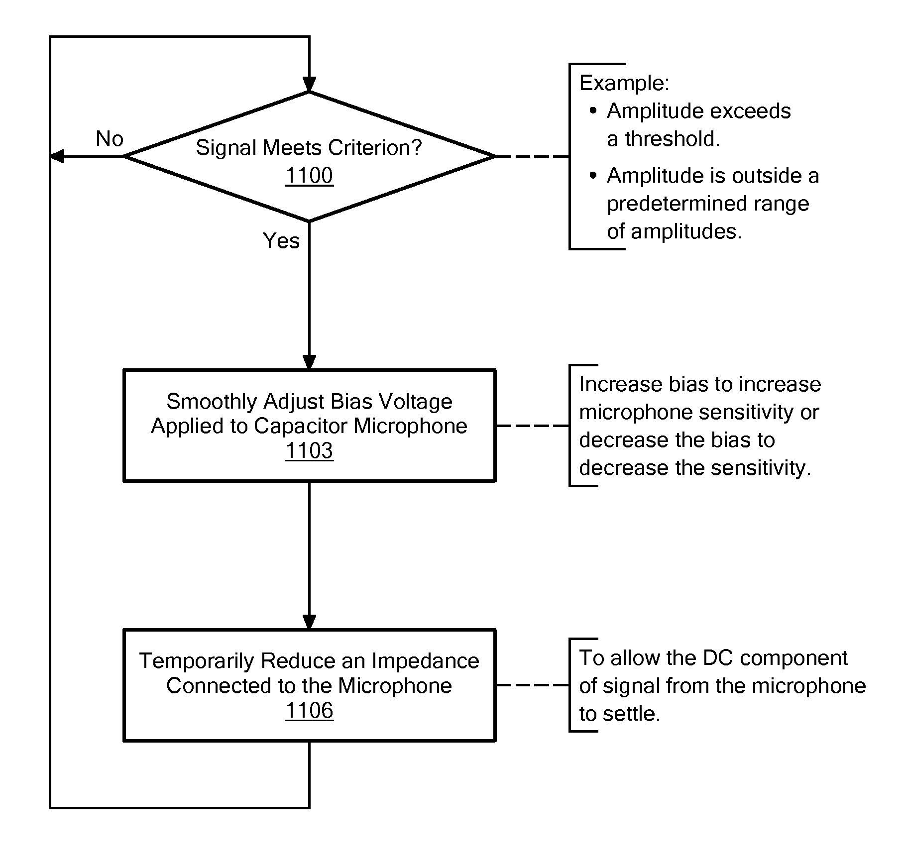
[0046]In accordance with embodiments of the present invention, methods and apparatus are disclosed for automatically adjusting sensitivity of a MEMS or other capacitor microphone by automatically dynamically adjusting a bias voltage applied to the capacitor microphone. “Dynamically” here means varying over time, not merely set or fixed, such as when a circuit is fabricated or put into service. Dynamic adjustments respond to, or at least partially compensate for, changes in circumstances, such as unpredictable changes in ambient noise. The sensitivity of the capacitor microphone may be automatically dynamically increased or decreased as need, such as in response to variations in the amplitude of a signal derived from the capacitor microphone. Thus, for example, under high ambient noise conditions, the sensitivity may be reduced to avoid clipping or distortion. On the other hand, the sensitivity may be automatically increased, such as when the microphone receives a low magnitude acous...


PUM


Abstract

A control circuit monitors a signal produced by a MEMS or other capacitor microphone. When a criterion is met, for example when the amplitude of the monitored signal exceeds a threshold or the monitored signal has been clipped or analysis of the monitored signal indicates clipping is imminent or likely, the control circuit automatically adjusts a bias voltage applied to the capacitor microphone, thereby adjusting sensitivity of the capacitor microphone.

Description

CROSS REFERENCE TO RELATED APPLICATIONS[0001]This application claims the benefit of U.S. Provisional Patent Application No. 61 / 286,364, filed Dec. 14, 2009, titled “MEMS Microphone with Programmable Sensitivity,” the entire contents of which are hereby incorporated by reference herein, for all purposes.TECHNICAL FIELD[0002]The present invention relates to MEMS (microelectromechanical system) systems, and more particularly to MEMS microphones with programmable sensitivity.BACKGROUND ART[0003]Microelectromechanical systems (MEMS) microphones are commonly used in mobile telephones and other consumer electronic devices, embedded systems and other devices. A MEMS microphone typically includes a conductive micromachined diaphragm that vibrates in response to an acoustic signal. The microphone also includes a conductive plate parallel to, and spaced apart from, the diaphragm with air or another dielectric between the conductive plate and the diaphragm. The diaphragm and the conductive plat...

Claims


Application Information

Patent Timeline
Patent Type & Authority Applications(United States)
IPC IPC(8): H03G3/00H04R11/04
CPCH04R3/00H04R19/005H04R2410/00H04R19/04H04R19/016
Inventor JOSEFSSON, OLAFUR MAR
Owner INVENSENSE
Why Eureka
Try Eureka