Luminescence Conversion LED

a technology applied in the field of led and led light conversion, can solve problems such as scattering losses, and achieve the effect of high conversion efficiency

Active Publication Date: 2011-06-16
OSRAM OLED
View PDF8 Cites 4 Cited by
  • Summary
  • Abstract
  • Description
  • Claims
  • Application Information

AI Technical Summary

Benefits of technology

[0007]It is an object of the present invention to provide a luminescence conversion LED that has a high conversion efficiency.

Problems solved by technology

Primary and secondary radiation is scattered on the powder particles of the phosphor, and this leads to scattering losses.

Method used


Image

  • Luminescence Conversion LED
  • Luminescence Conversion LED
  • Luminescence Conversion LED

Examples


Embodiment Construction

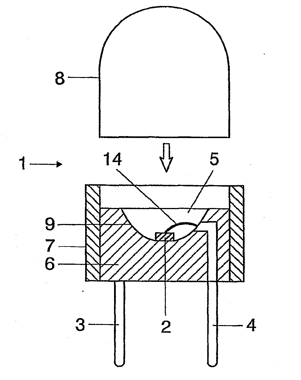
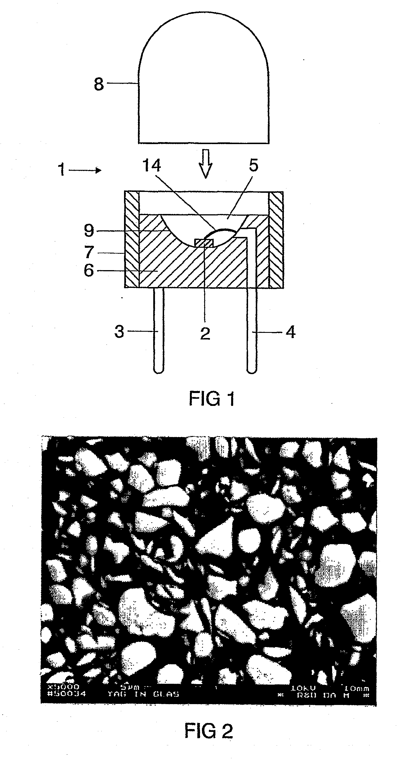
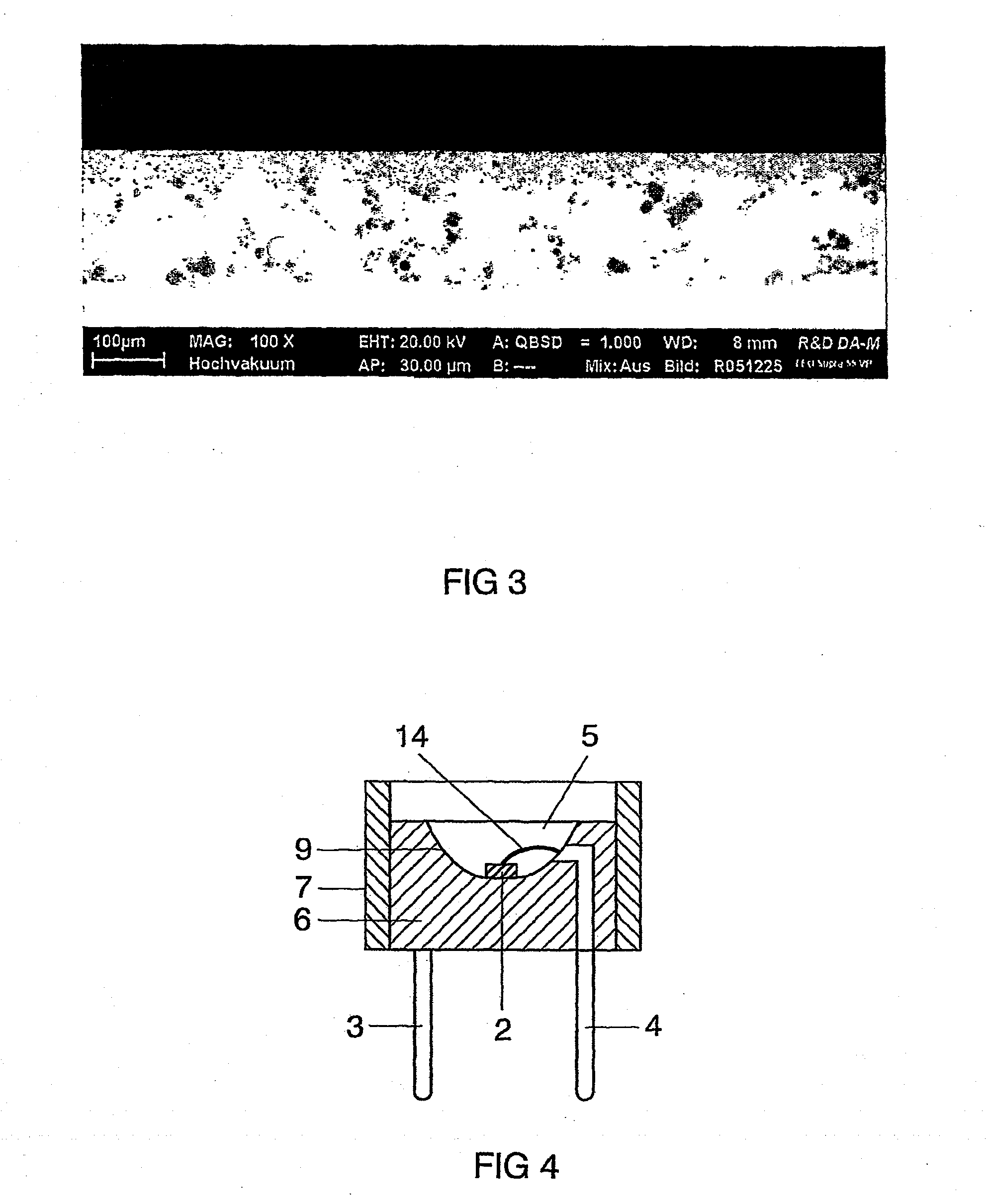
[0034]A design such as is described in U.S. Pat. No. 5,998,925, for example, is employed for use in a white LED together with an InGaN Chip. The design of such a light source for white light is shown explicitly in FIG. 1. The light source is a semiconductor component (chip 1) of type InGaN with a peak emission wavelength of 460 nm and having a first and second electrical connection 2, 3 that is embedded in an opaque basic housing 8 in the region of a cutout 9. One of the connections 3 is connected to the chip 1 via a bonding wire 14. The cutout has a wall 17 that serves as reflector for the blue primary radiation of the chip 1. The cutout 9 is filled with a casting compound 5 that contains the components of glass and phosphor pigments 6. The phosphor pigments are, for example, a mixture of a number of pigments, including YAG:Ce. An alternative is TbAG:Ce. Production takes place according to one of methods 1 and 2.

[0035]The REM picture in FIG. 2 shows a cross section of a solid phosp...


PUM


Abstract

A luminescence conversion LED having a radiation emitting chip that is connected to electrical connections and is surrounded by a housing that comprises at least a basic body and a cap, the chip being seated on the basic body, in particular in a cutout of the basic body, and the primary radiation of the chip being converted at least partially into longer wave radiation by a conversion element, wherein the cap is formed by a vitreous body, the conversion means being contained in the vitreous body, the refractive index of the vitreous body being higher than 1.6, preferably at least n=1.7.

Description

CROSS REFERENCE TO RELATED APPLICATIONS[0001]This application is a Divisional of U.S. patent application Ser. No. 11 / 920,757 which was filed with the U.S. Patent and Trademark Office on Nov. 19, 2007. This application claims the priority of German patent application no. 10 2005 023 134.9 filed May 19, 2005, the content of which is hereby incorporated by reference.BACKGROUND OF THE INVENTION[0002]1. Field of the Invention[0003]The present invention relates to a luminescence conversion LED and, in particular, an LED with a high efficiency of conversion.[0004]2. Description of the Related Art[0005]US-A 2003 / 025449 has already disclosed a luminescence conversion LED in which the phosphor is embedded in an environment made from glass containing material. This exhibits higher stability than the usual resins or silicones, above all in the case of chips that emit shortwave primary radiation in the UV or blue spectral region. Glass, glass ceramic or silica glass is to be regarded as suitable...

Claims


Application Information

Patent Timeline
Patent Type & Authority Applications(United States)
IPC IPC(8): H01J9/22H01L33/50H01L33/58
CPCH01L33/505H01L2224/48091H01L2224/48247H01L2924/00014
Inventor BECKER, DANIELBRUNNER, HERBERTFIEDLER, TIMSTRAUJORGZACHAU, MARTIN
Owner OSRAM OLED
Why Eureka
Try Eureka