UV LED based lamp for compact UV curing lamp assemblies

a technology of led-based lamps and curing lamps, which is applied in the direction of drying solid materials, baking ovens, drying machines, etc., can solve the problems of large manufacturing and distribution infrastructure, large amount of wasted light energy that does not strike the work product, and bulky uv-emitting electrodeless lamps, etc., to achieve the effect of increasing the total irradiance of the uv led-based optical component assembly

Inactive Publication Date: 2011-06-23
HERAEUS NOBLELIGHT AMERICA
View PDF2 Cites 50 Cited by
  • Summary
  • Abstract
  • Description
  • Claims
  • Application Information

AI Technical Summary

Benefits of technology

[0011]The above-described problems are addressed and a technical solution is achieved in the art by providing an ultraviolet (UV) LED-based lamp for UV curing lamp assemblies. An array of UV emitting LEDs are packaged together and arranged along the length of at least one optical component configured to focus UV radiation (e

Problems solved by technology

Microwave-powered, UV-emitting electrodeless lamps are bulky, noisy, and require a large manufacturing and distribution infrastructure due to many consumable parts, since the service lifetime of an electrodeless lamp is relatively short.
With present day optics, the focused beam width of an electrodeless lamp is at best about 1 centimeter (co

Method used


Image

  • UV LED based lamp for compact UV curing lamp assemblies
  • UV LED based lamp for compact UV curing lamp assemblies
  • UV LED based lamp for compact UV curing lamp assemblies

Examples


Embodiment Construction

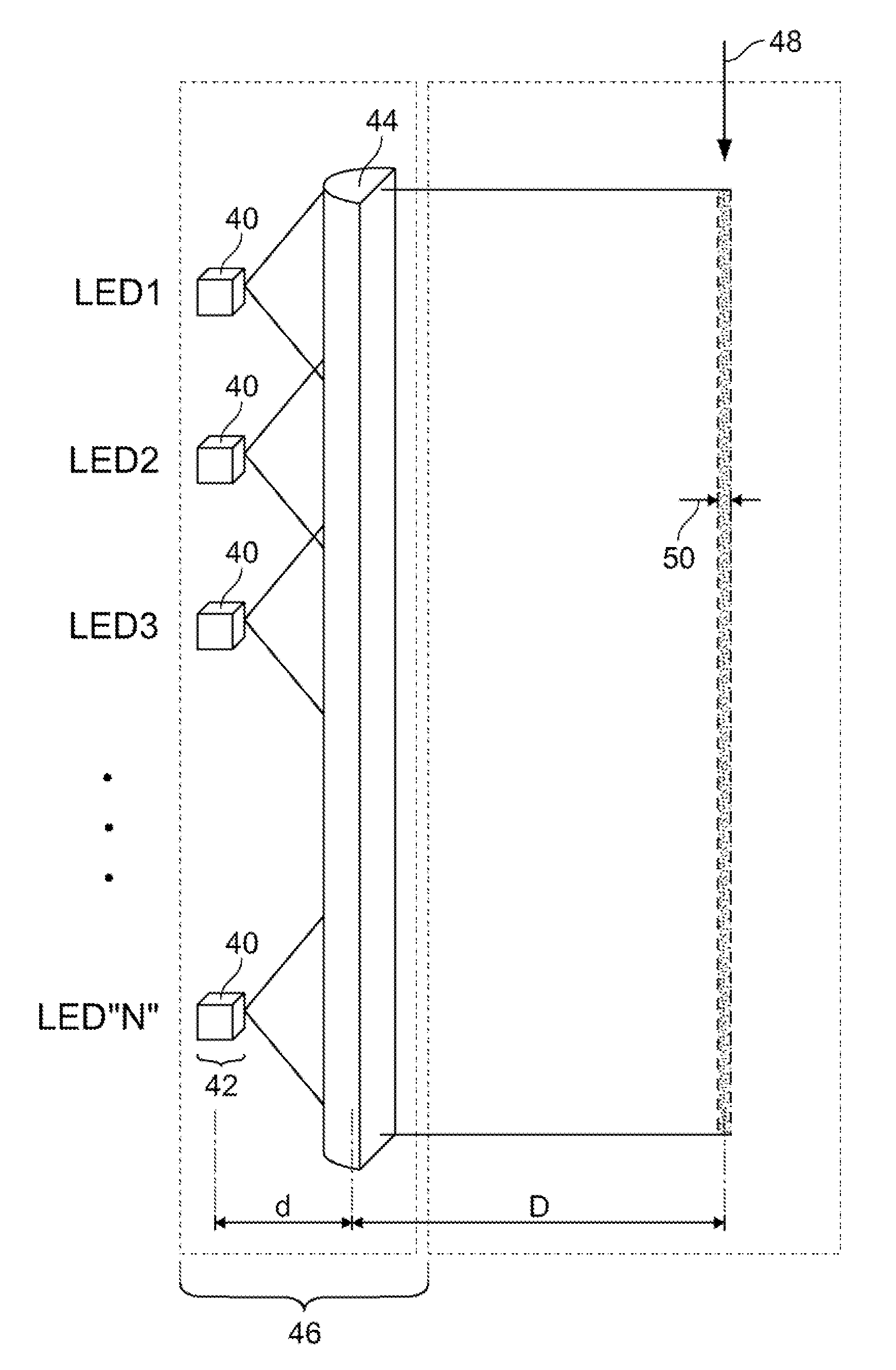
[0025]FIG. 4 shows a side view of a geometric arrangement of a UV LED array assembly for curing work products, e.g., optical fibers, according to an embodiment of the present invention. A plurality of UV emitting LED dies 40 are packaged together in a linear array 42, LEDI-LED “N”. The UV LED dies 40 may emit a single or plurality wavelengths of light below 450 nm.

[0026]The UV LED dies 40 may be packaged with one or more optical components 44. The optical components 44, for example, may be, but are not limited to, refractive optics (e.g., lens, prism, etc.), reflective optics (e.g., mirrors), adaptive optics, metamaterials, etc. In a preferred embodiment, the one or more optical components 44 is a cylindrical lens 44 that may be removably attached to the UV LED array 42 or affixed to the UV LED dies 40 to form a UV LED-based optical component assembly 46. The UV LED-based optical component assembly 46 may be made to be modular, i.e., having a specific length and a specific number of...


PUM

PropertyMeasurementUnit
Lengthaaaaaaaaaa
Transparencyaaaaaaaaaa
Distanceaaaaaaaaaa

Abstract

An ultraviolet (UV) LED-based lamp for UV curing lamp assemblies is disclosed. An array of UV emitting LEDs are packaged together and arranged along the length of a cylindrical lens to form a UV LED-based optical component assembly. The UV LED-based optical component assembly may be made to be modular. A UV LED lamp assembly may comprise a plurality of UV LED-based optical component assemblies arranged around a workpiece tube. The workpiece tube may be filled with an inert gas and may be made of quartz or glass. One or more curved back reflectors may be placed opposite the LED UV LED-based optical component assemblies to collect UV light escaping the workpiece tube and refocus the light to the other side of the workpiece. The UV LEDs may be arranged on a single surface or a multi-level tiered platform.

Description

CROSS-REFERENCE TO RELATED APPLICATION[0001]This application claims the benefit of U.S. provisional patent application No. 61 / 289,518 filed Dec. 23, 2009, the disclosure of which is incorporated herein by reference in its entirety.FIELD OF THE INVENTION[0002]The invention relates generally to ultraviolet (UV) curing lamp assemblies, and more particularly, to a light-emitting diode (LED)-based lamp for UV curing lamp assemblies.BACKGROUND OF THE INVENTION[0003]Radiant energy is used in a variety of manufacturing processes to treat surfaces, films, and coatings applied to a wide range of materials. Specific processes include, but are not limited to, curing (i.e., fixing, polymerization), oxidation, purification, and disinfection. Processes employing radiant energy to polymerize or effect a desired chemical change are rapid and often less expensive compared to a thermal treatment. The radiation can also be localized to control surface processes and allow preferential curing only where ...

Claims


Application Information

Patent Timeline
IPC IPC(8): H05B3/00
CPCB01J19/123H05B3/0057B05D3/067F21K2/00F21Y2115/10H01L31/12H05B3/00
Inventor LEONHARDT, DARRINWOOD, CHARLES H.SWAIN, PRADYUMNA K.
Owner HERAEUS NOBLELIGHT AMERICA
Why Eureka
Try Eureka