Underwater turbine with finned diffuser for flow enhancement

Inactive Publication Date: 2011-06-23
KINETIC HARVEST
View PDF19 Cites 22 Cited by
  • Summary
  • Abstract
  • Description
  • Claims
  • Application Information

AI Technical Summary

Benefits of technology

[0008]A preferred aim of this invention, therefore, is to provide a new and improved shroud with forward cowling, center duct section, and aft diffu

Problems solved by technology

The use of a shroud requires that the flow inside the shroud should not separate or the pressure differential enhancement effect will be lost.
A potential problem with these holes though is increased cost to manufacture while t

Method used


Image

  • Underwater turbine with finned diffuser for flow enhancement
  • Underwater turbine with finned diffuser for flow enhancement
  • Underwater turbine with finned diffuser for flow enhancement

Examples


first embodiment

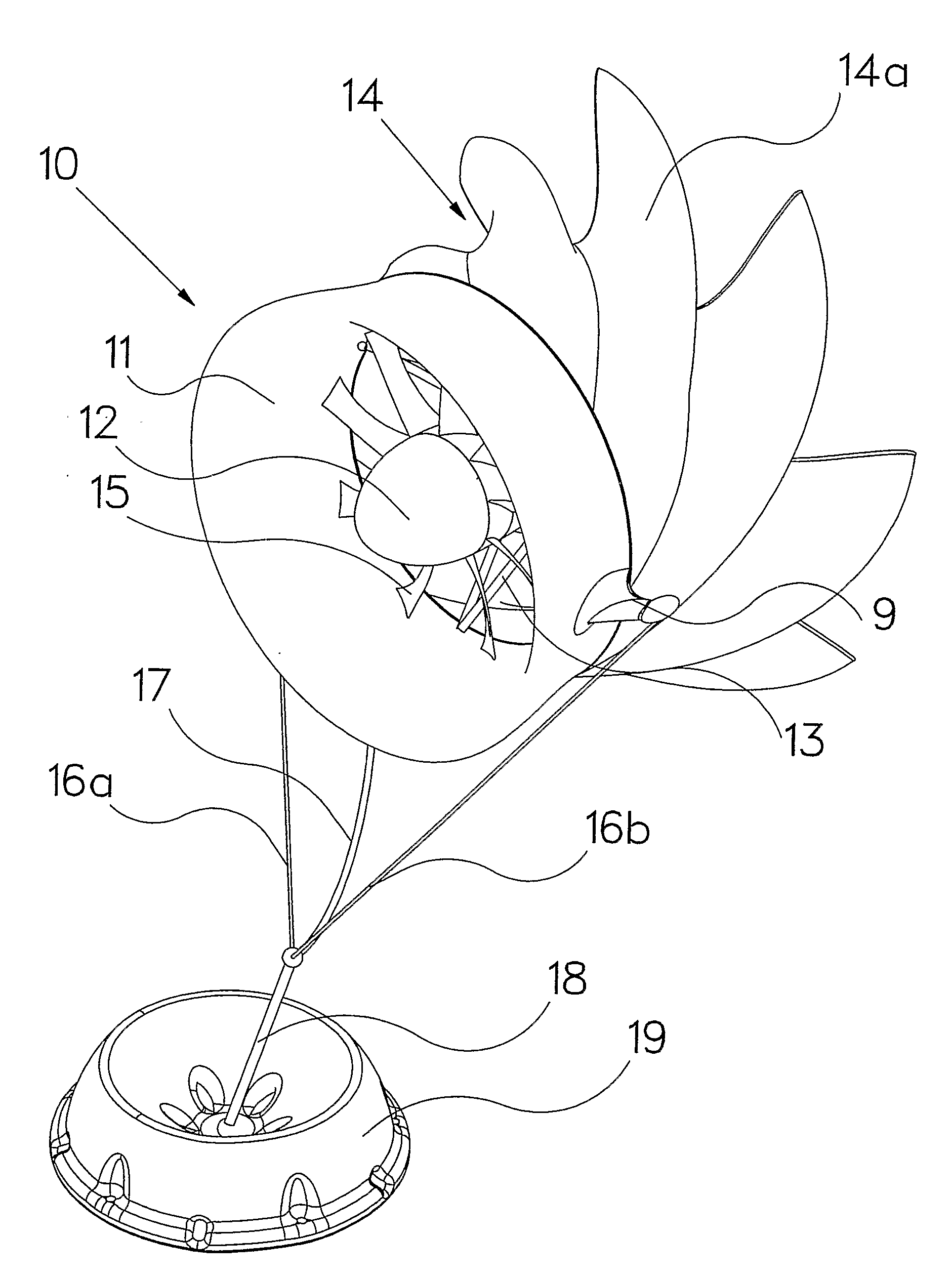
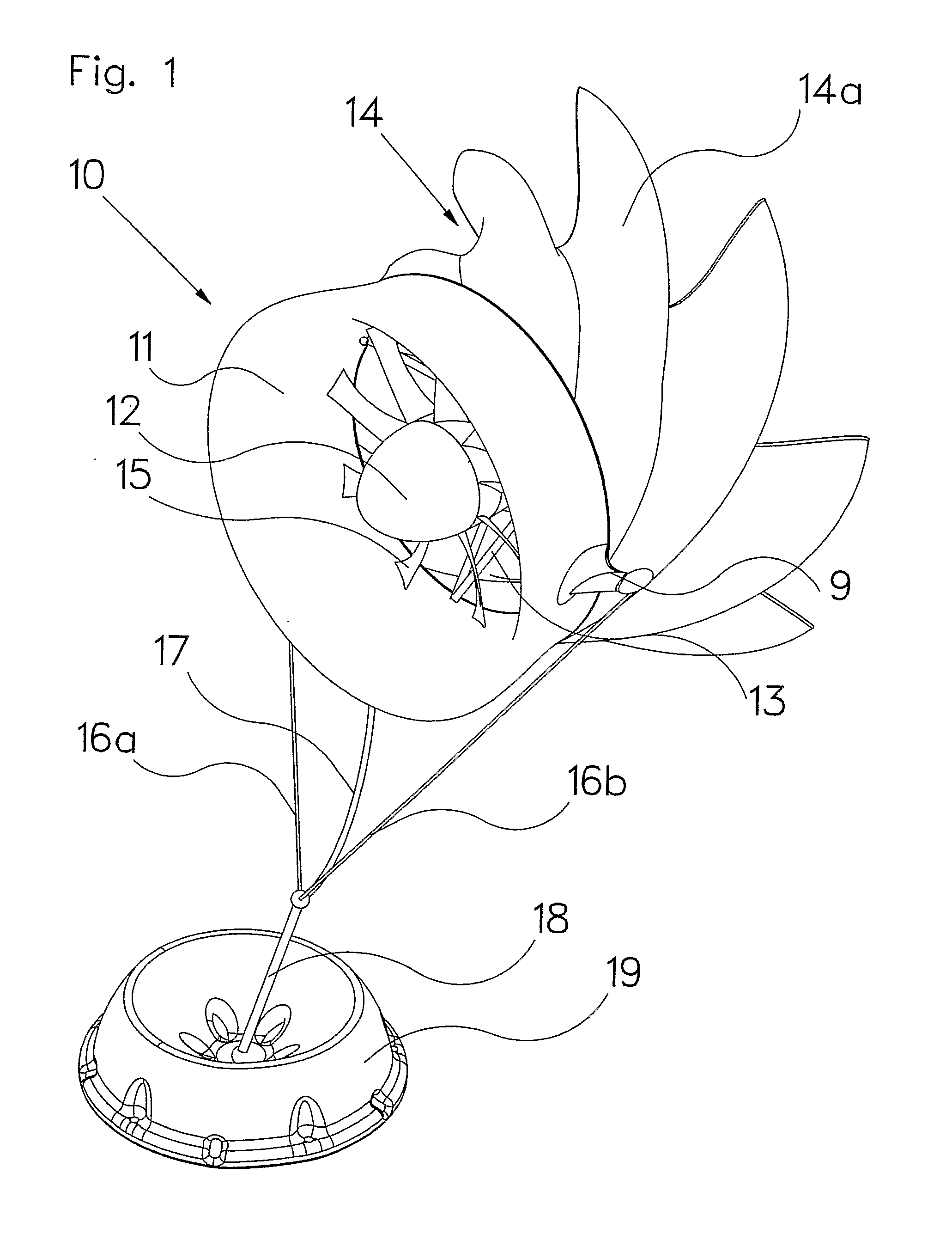
[0069]FIG. 1 shows the invention 10, a submerged tethered turbine generator system. The cowling and duct 11 appear normal enough as is known skilled in the art but the aft diffuser 14 has vanes (fins) such as 14a which cause it to rotate and accelerate the flow through the duct. The augmented flow passes through the center of the shroud past the turbine blades 15 which are optimized for flow inside a duct. To maximize underwater system reliability, they should be fixed pitch, but if maximum efficiency is needed, particularly for larger system operating where currents vary, they could be made variable pitch. The turbine blades spin a generator in the core 12 which is held to the duct by struts 13. The struts can be very thin like spokes to minimally impact the flow, or they could be in the form of stator blades to further enhance the flow.

[0070]The diffuser 14 may be attached to the duct such as to be able to spin freely on its axis by various means. In one embodiment the diffuser is...

embodiment 30

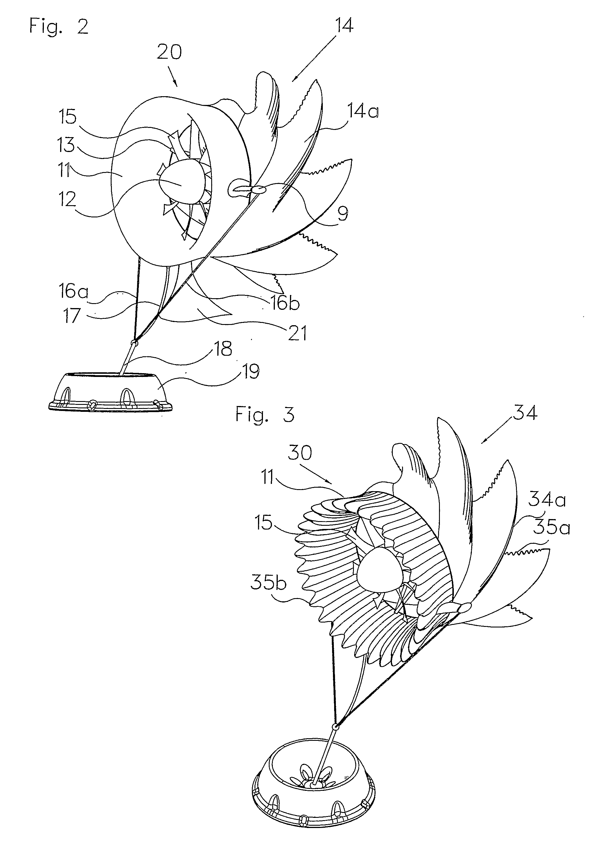
[0075]FIGS. 3, 4a, and 4b show another embodiment 30 of the invention with added ribs 34 and protrusions 35a on the fins 14a to further enhance flow control. Note that the fins are thin structures such that there is an interior space 36 that helps to create the swirling action that in effect pumps water through the inside of the cowling and duct 31 so more power can be extracted by the blades 35 from the flowstream. In addition, protrusions 35b on the leading edge of the cowling and duct 31 further add to flow performance as inspired by nodules on whales. These “tubercles” (bumps) can be placed on the leading edge of the cowling and duct 31 can reduce leading edge drag and help suck in the flow over the lip of the cowling (diffuser). As an example from nature, see www.whalepower.com, and is also described in relation to wings rather than the herein discussed cowl in US pending patent publication number US2006 / 0060721, published Mar. 23, 2006.

embodiment 40

[0076]In the above figures and embodiments, the diffusers are generally rotating but can be fixed to the duct. FIGS. 5 and 6 show an embodiment 40 specifically designed to be of a non-rotating diffuser type. The base 19 is anchored to the seafloor as before, and tethers 46a and 46b attached to anchor wings 49 hold the system 40 to the base 19 via a line 48. Tubercles 75b help to augment the flow into the cowling. The flow enters the cowling and duct 41 and flows past the turbine blades 45 causing them to spin and generate power. Power generated by the turbine in center structure 42 which is held to the duct 41 by struts 43 is transmitted via cable 47. The aft diffuser section 44 has fixed fins such as 44a with ridges 74 and bumps 75a to further enhance the flow.

[0077]FIG. 7 shows the embodiment of FIG. 5 with an added winglet 50 attached to the ends of the fins 44a. This winglet further enhances the flow, although in an underwater environment, it may need to be periodically cleaned ...


PUM


Abstract

A submerged flow augmented shrouded turbine power generation system with a forward flow compression section (11) and an aft multi-finned diffuser section (14) with a centrally supported generator (12) powered by turbine blades (15) optimized to be driven by the enhanced flow field created by the forward cowl and aft diffuser/fin sections. The system can be positively buoyant and tethered to the seafloor (18) or negatively buoyant and tethered to the underside of a vessel or offshore structure, or it can be attached directly to the underside of a vessel or offshore structure. An array of such systems can be placed on the seafloor to create a distributed power generation network. An array of such systems can also be placed on the seafloor to directly pump seawater to an energy storage device or a central desalination plant.

Description

FIELD OF THE INVENTION[0001]The present application relates to the use of hydrodynamic devices to enhance the pressure differential across an underwater fluid turbine to increase the power yield per unit area. The present application discloses an underwater fluid turbine encased in a multi dimensional shroud to enhance the pressure differential across the turbine for generating electricity thereby augmenting turbine efficiency and reducing the turbine diameter required to generate a desired amount of power.BACKGROUND OF THE INVENTION[0002]The use of a shroud to accelerate water through a turbine is a well-known and practiced discipline. In the open ocean, the harnessing of currents has been dominated by large bladed turbines, analogous to wind turbines on land. In fact, on land, Diffuser Augmented Wind Turbines (DAWTs) have been known for many years to enable blade diameter to be smaller because they create a greater pressure differential across the blade, so blade speed is increase...

Claims


Application Information

Patent Timeline
IPC IPC(8): F01D15/10F03G7/00
CPCF03B3/04F03B3/18F03B17/061F03D1/04F05B2240/12F05B2240/13Y02E10/728F05B2240/14F05B2240/917F05B2240/97F05B2250/611Y02E10/223Y02E10/28F05B2240/133F05B2240/9176Y02E10/20Y02E10/72F03D9/25F03D13/20
Inventor BAILEY, RALPH-PETER
Owner KINETIC HARVEST
Why Eureka
Try Eureka