

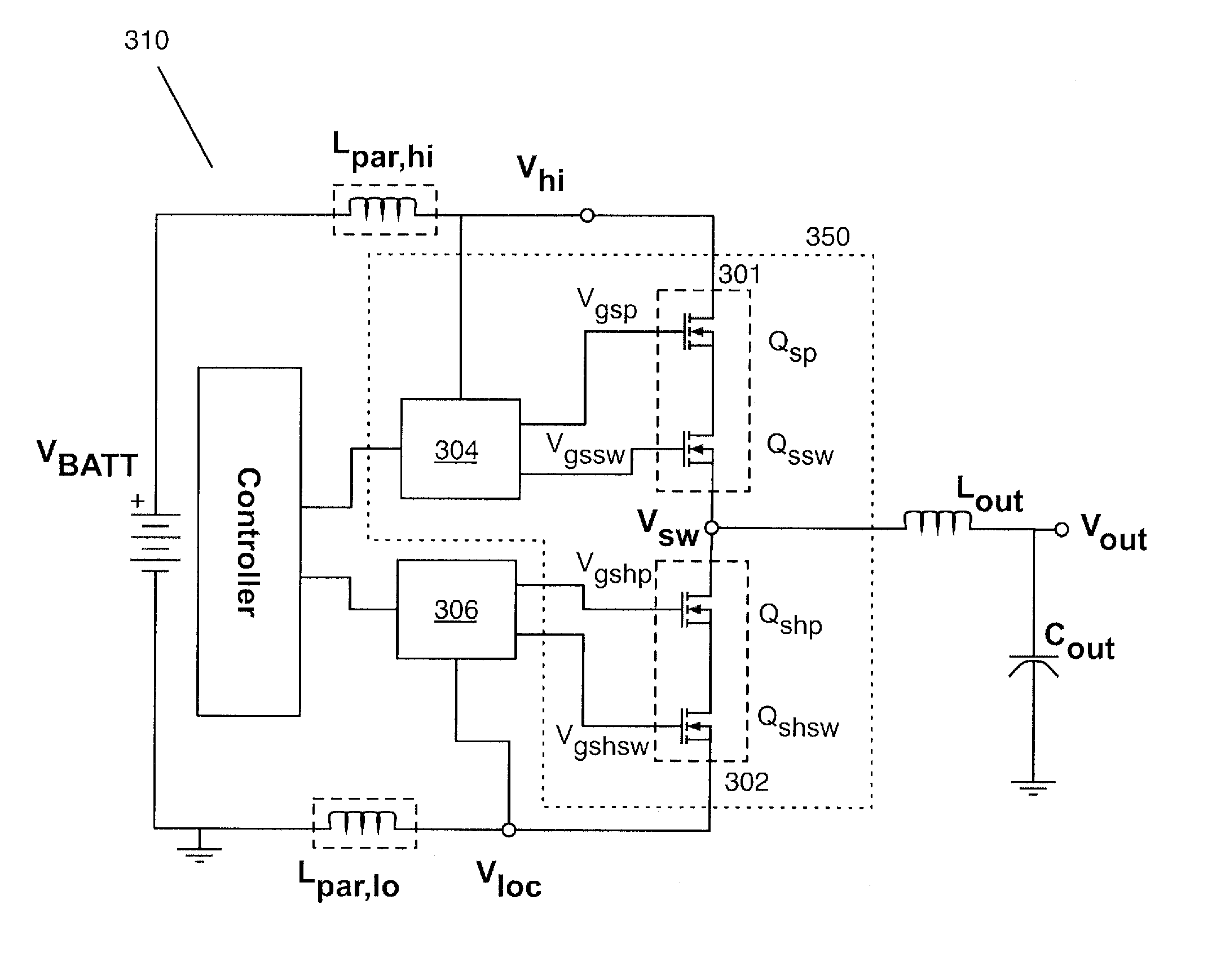
Over Voltage Protection of a Switching Converter
a switching converter and over voltage protection technology, applied in the field of power conversion, can solve the problems of linear regulators that can only reduce and not increase voltage, linear regulators are very inefficient in many applications, and have two important limitations
- Summary
- Abstract
- Description
- Claims
- Application Information
AI Technical Summary
Problems solved by technology
Method used
Image

Examples
Embodiment Construction
[0001]The described embodiments relate generally to power conversion. More particularly, the described embodiments relate to over voltage protection of a switching converter.
BACKGROUND
[0002]DC voltage converters and regulators are well-known in the art and are widely employed to ensure that the DC voltage provided to electronic devices is of the correct value independent of variations in the available supply voltage or the load presented by the device being powered. For example, most battery-operated consumer electronics devices use DC-DC regulators to convert the 2.7-5.5 V battery voltage down to a 0.56-3.4 V operating voltage required by the on-board integrated circuits. Voltage regulators are universally used to convert the battery voltage to the desired fixed value to be supplied to the integrated circuit, and to ensure that value remains constant as the battery ages and the current used by the integrated circuit changes.
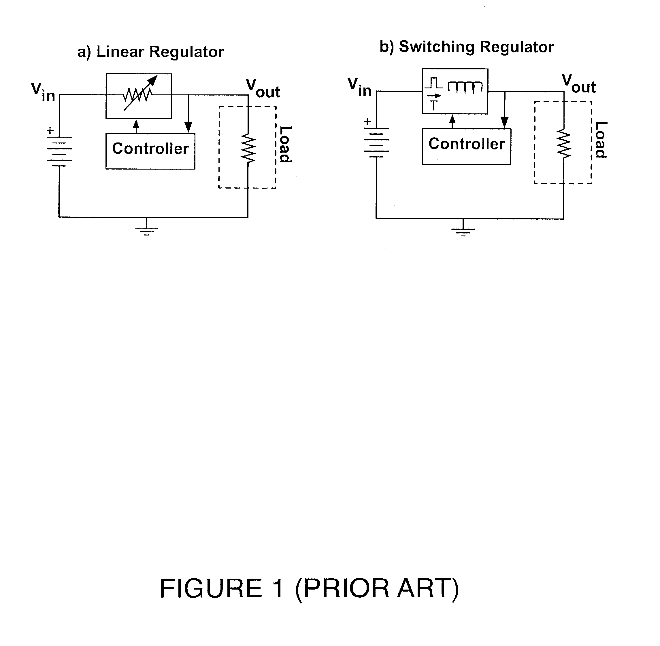
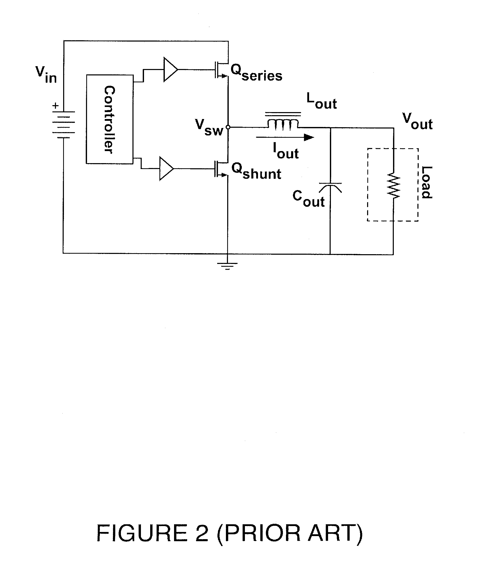
[0003]Voltage regulators can be classified as either linea...
PUM
 Abstract
Description
Claims
Application Information