Low capacitance probe for testing circuit assembly

a low capacitance, circuit assembly technology, applied in the direction of printed circuit testing, instruments, measurement devices, etc., can solve the problems of increasing the likelihood of errors, not widely used for certain types of components, and sockets that have not been widely tested using capacitive test techniques, etc., to reduce capacitance, reduce capacitance, and reduce capacitance

Active Publication Date: 2011-06-23
TERADYNE
View PDF50 Cites 9 Cited by
  • Summary
  • Abstract
  • Description
  • Claims
  • Application Information

AI Technical Summary

Benefits of technology

[0010]A probe for capacitive testing in a low signal environment is provided by reducing capacitance between a sense plate and a guard plate of the probe. Reduced capacitance may be achieved through the shape of the guard plate. For example, the guard plate may have a plurality of holes, which reduce the capacitance between the guard and sense plate. Reducing this capacitance increases the magnitude of the signal coupled to the sense plate from the test pin when the probe is used as part of a system for testing circuit assemblies.

Problems solved by technology

Though capacitive testing may be desirable, it has not been widely used for certain types of components.
For example, sockets have not been widely tested using capacitive test techniques.
Accordingly, even when a pin under test is properly connected to a circuit assembly, it is difficult to reliably detect a capacitively coupled test signal, increasing the likelihood of errors when testing pins of a socket capacitively.
However, inserting a probe into the cavity introduces a substantial risk of contacting and damaging the pins.
The guard plate shields the sense plate from electrical noise that could change the signal detected at the sense plate enough to produce an erroneous test result.

Method used


Image

  • Low capacitance probe for testing circuit assembly
  • Low capacitance probe for testing circuit assembly
  • Low capacitance probe for testing circuit assembly

Examples


Embodiment Construction

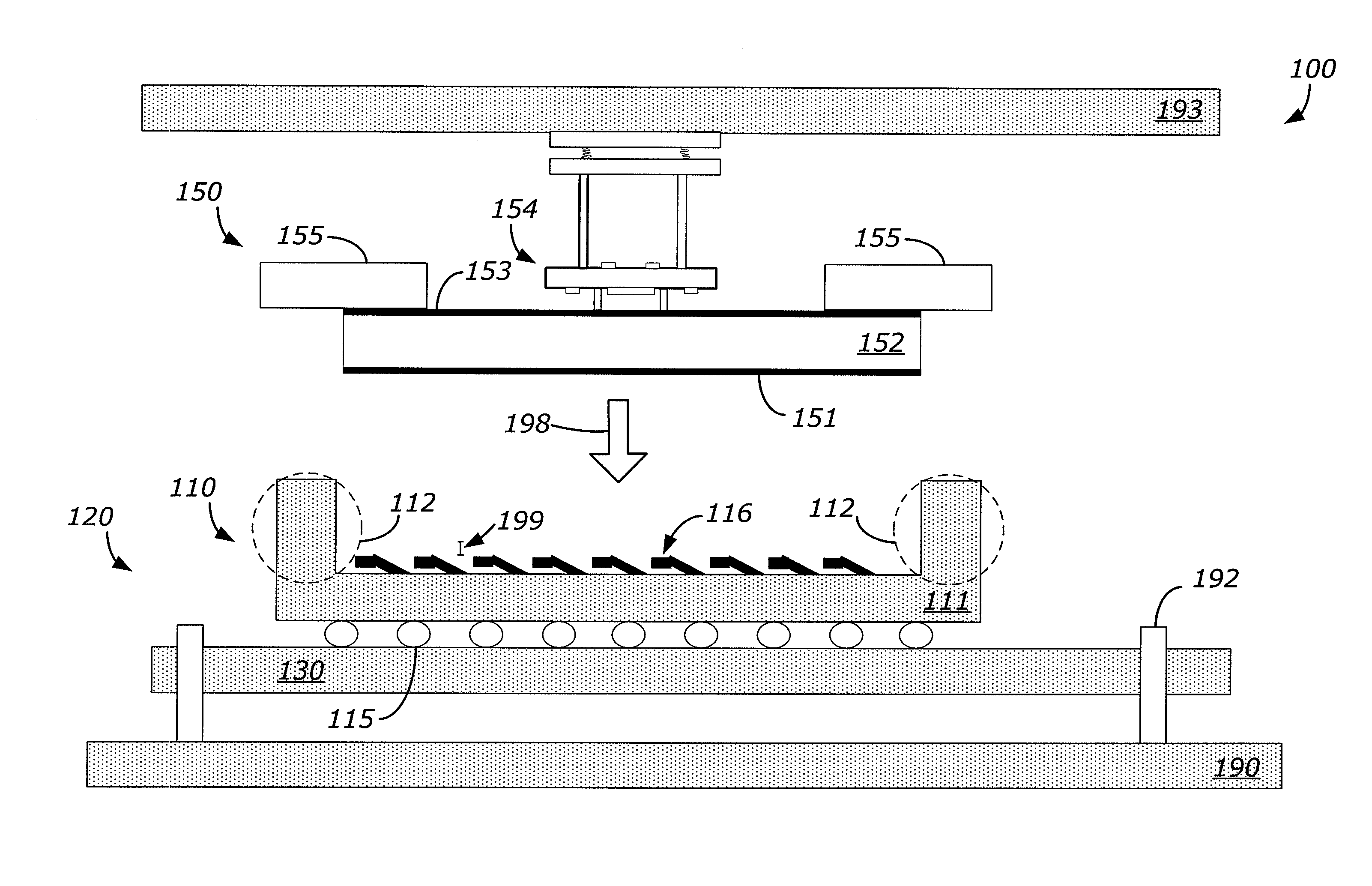
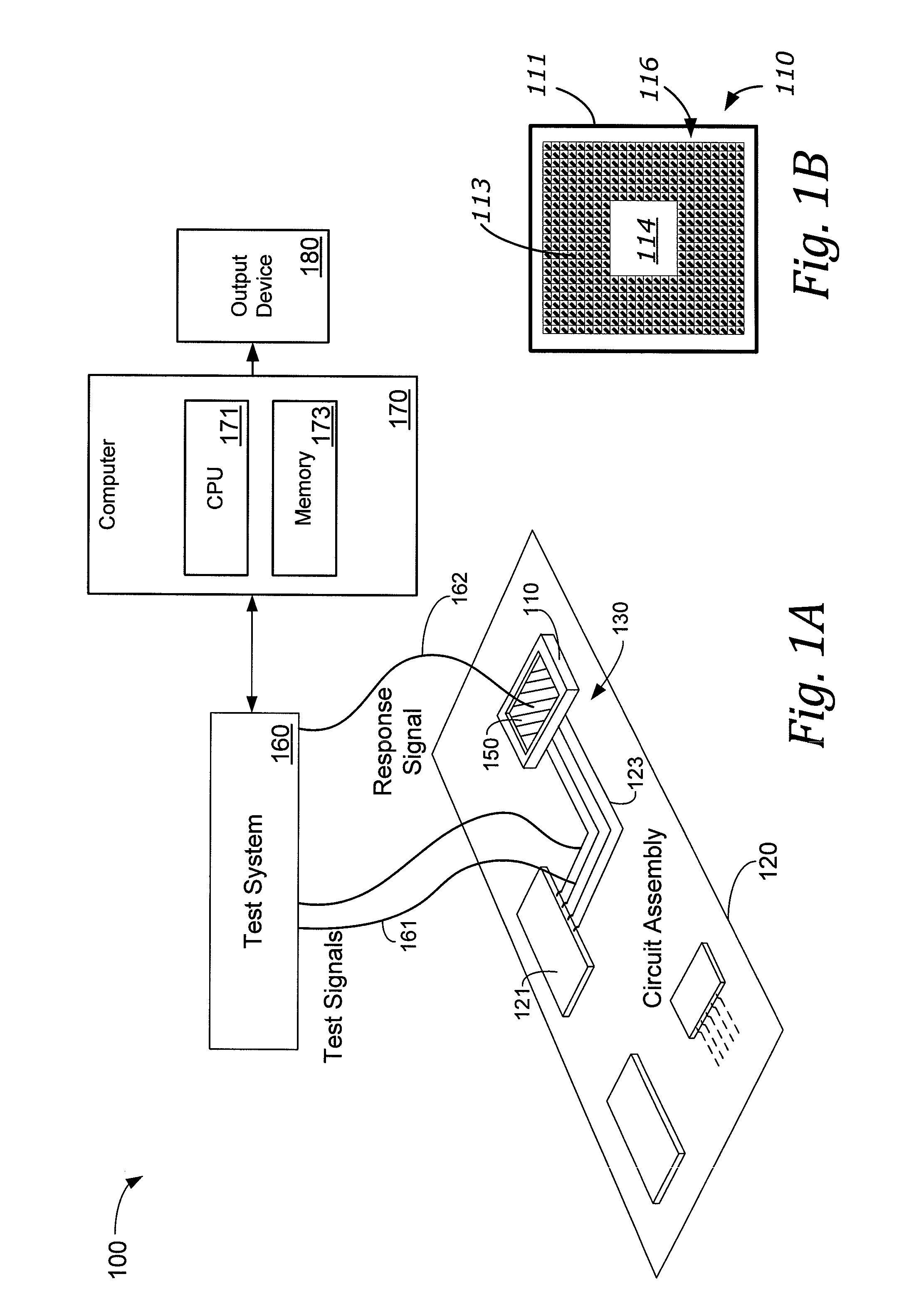
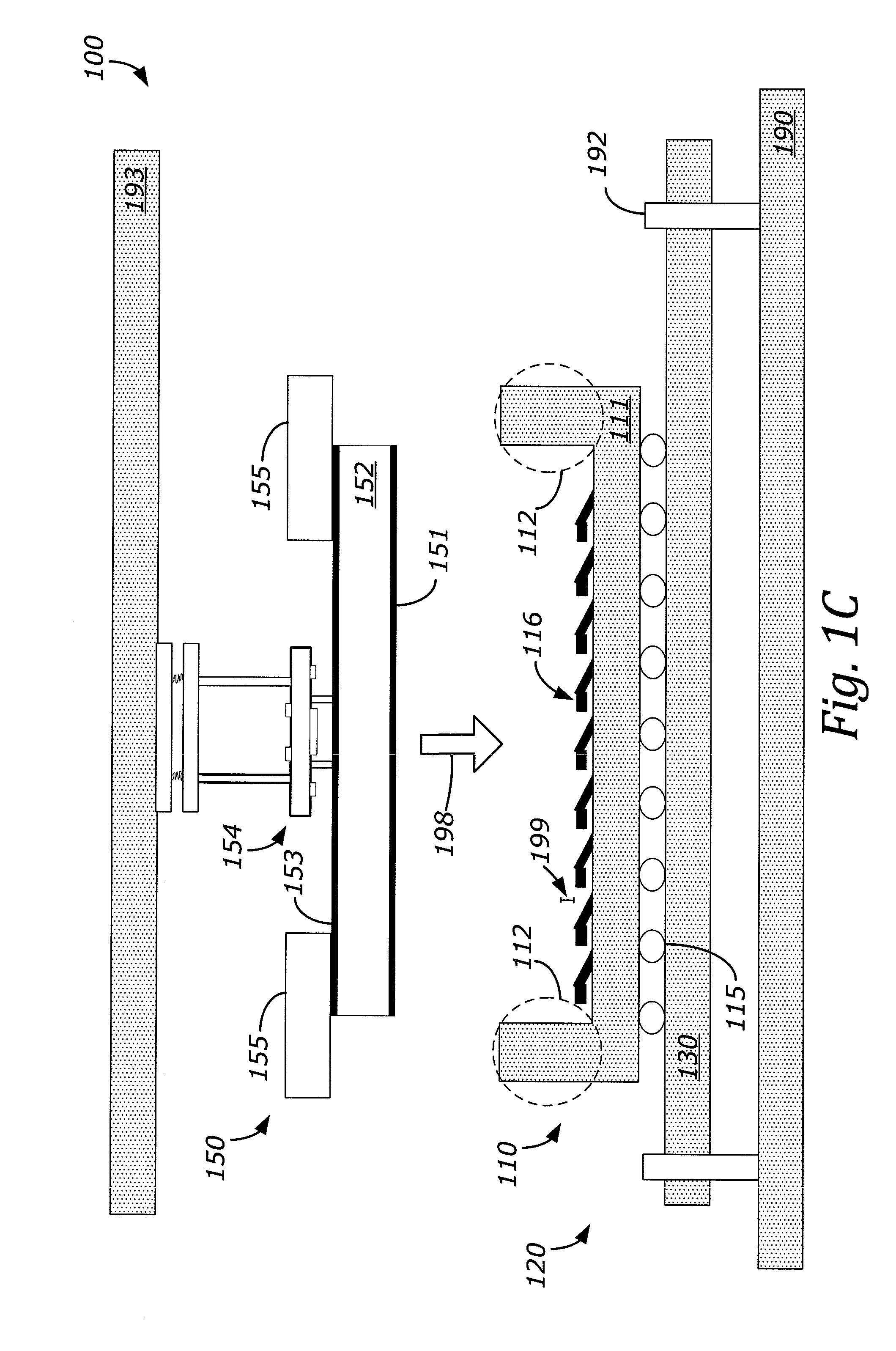
[0039]The inventor has recognized and appreciated that capacitive opens testing for some types of circuit components, including chip sockets, has been limited because of the risk of damaging the components during the testing process which has led to the test probe being separated from the component under test by too great a distance for a test signal to be reliably detected. The inventor has recognized and appreciated that capacitive testing can be made feasible by reducing the risk of damage to components by using spacers to ensure proper alignment of a test probe with a respective component of a circuit assembly to be tested. Such spacers may be configured to ensure that when a probe assembly is moved into the testing position, a gap of predetermined size exists between the probe assembly and the pins of the component. In addition to ensuring the proper vertical spacing (i.e., a gap), the spacers may be configured to assist in the lateral alignment of the probe with the component....


PUM


Abstract

An improved system for capacitive testing electrical connections in a low signal environment. The system includes features that increase sensitivity of a capacitive probe. One feature is a spacer positioned to allow the probe to be partially inserted into the component without contacting the pins. The spacer may be a collar on the probe that contacts the housing of the component, contacts the substrate of the circuit assembly, or both. In some other embodiments, the spacer may be a riser extending beyond the surface of the sense plate that contacts the component, a riser portion of the component, or a combination of both. The spacer improves sensitivity by establishing a small gap between a sense plate of the probe and pins under test without risk of damage to the pins.
A second feature is a guard plate of the probe with reduced capacitance to a sense plate of the probe. Reducing capacitance also increases the sensitivity of the probe.

Description

BACKGROUND[0001]1. Field of the Invention[0002]The invention relates generally to testing of circuit assemblies, and more particularly to capacitive testing of connections to pins of components of the circuit assembly.[0003]2. Description of Related Art[0004]During the manufacture of printed circuit board (PCB) assemblies, testing is performed at one or more stages to ensure that the finished product functions adequately.[0005]In some manufacturing operations, circuit assemblies are first tested before any components are mounted to them. The components may be separately tested before they are attached to the circuit assemblies, usually by soldering. Once the components are attached, a further test may be performed to verify that the components are properly attached. Such testing includes “opens” tests and “shorts” tests that indicate defects in attachment of contact points of the components to the circuit assembly. These contact points are generally referred to as “pins,” even thoug...

Claims


Application Information

Patent Timeline
Patent Type & Authority Applications(United States)
IPC IPC(8): G01R31/02
CPCG01R31/304G01R31/2808G01R31/312
Inventor SUTO, ANTHONY J.
Owner TERADYNE
Why Eureka
Try Eureka