

Ball joint and method of manufacturing same
a technology of ball joints and manufacturing methods, applied in the field of ball joints, can solve the problems of deformation, deformation, and deformation of the function of the ball portion as a ball joint, and achieve the effect of not greatly increasing the production cost and increasing the pull-out load
- Summary
- Abstract
- Description
- Claims
- Application Information
AI Technical Summary
Benefits of technology
Problems solved by technology
Method used
Image

Examples
Embodiment Construction
Structure of Ball Joint
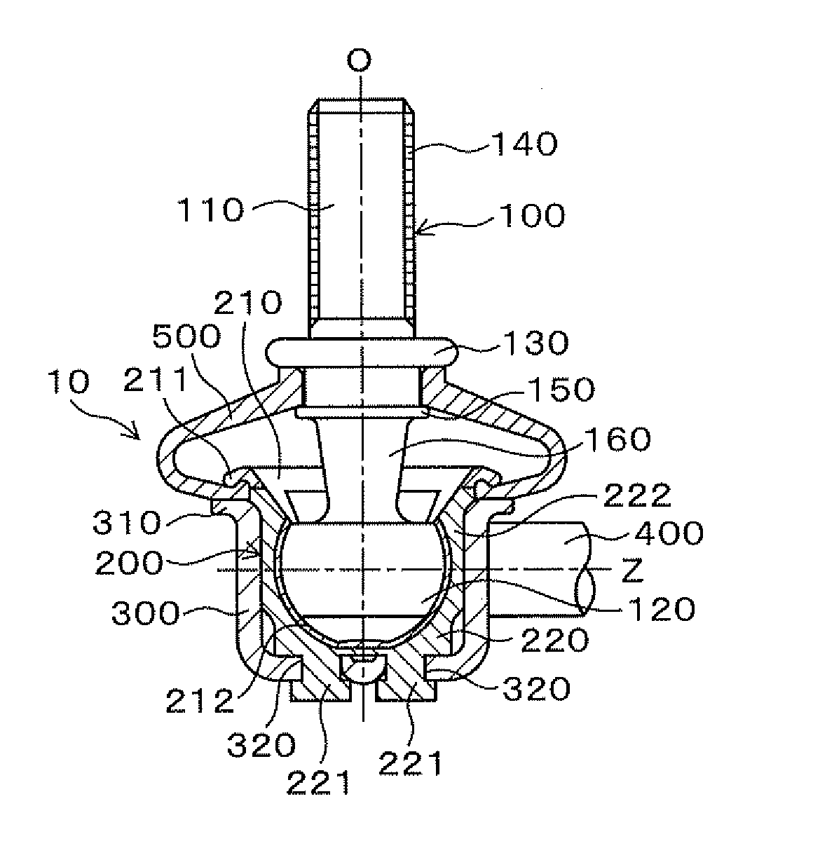
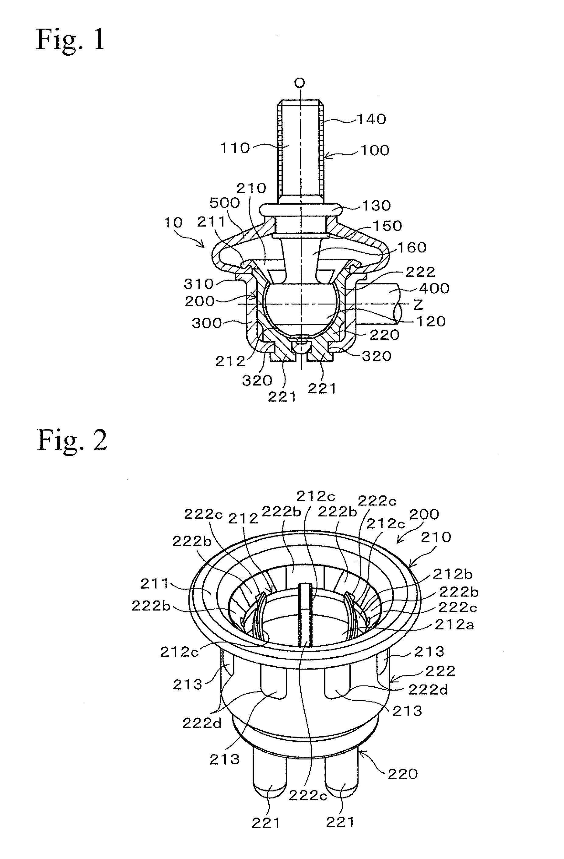
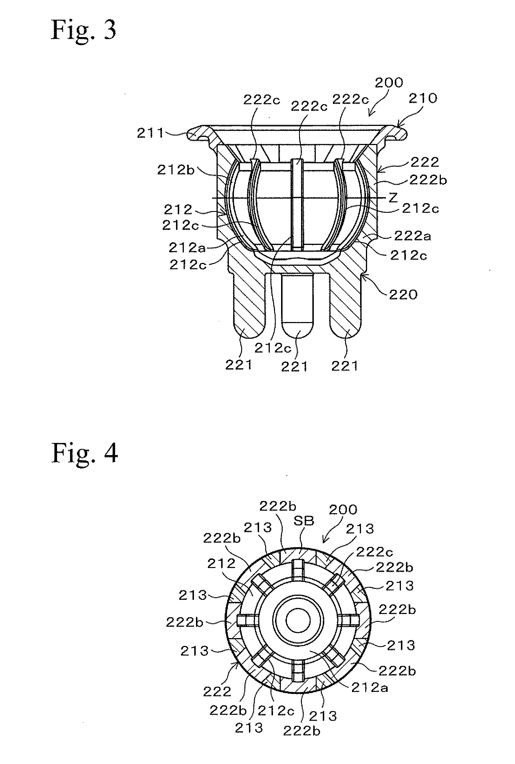
[0033]An embodiment of the present invention will be described with reference to the drawings hereinafter. FIG. 1 is a cross section showing a ball joint. FIG. 2 is a perspective view showing a ball seat. FIG. 3 is a longitudinal cross section showing a ball seat. FIG. 4 is a transverse cross section showing a ball seat. FIG. 5 is a view showing a reinforcing portion, viewed from the bottom. FIG. 6 is a perspective view showing a ball receiving portion. FIG. 7 is a perspective view showing a reinforcing portion.
[0034]As shown in FIG. 1, a ball joint 10 is equipped with a ball stud 100, a ball seat 200, a housing 300, a support bar 400, and a dust cover 500. The ball joint 10 has the ball stud 100, the ball seat 200, the housing 300, and the support bar 400 as main components. The ball seat 200 universally and pivotally supports the ball stud 100. The ball joint 10 is secured to a plate-like mounting member (not shown in the figures). The ball joint 10 may be u...
PUM
| Property | Measurement | Unit |
|---|---|---|
| Diameter | aaaaa | aaaaa |
| Width | aaaaa | aaaaa |
| Height | aaaaa | aaaaa |
Abstract
Description
Claims
Application Information