
Exterior heat insulation panel

a technology for exterior heat insulation and panels, applied in heat insulation, lighting and heating apparatus, heating types, etc., can solve the problems of slow spread of exterior heat insulation buildings, reduced air-conditioning efficiency, and limited methods of exterior heat insulation, so as to achieve the desired strength, improve water retentivity, and shape retentivity for a long time.

Inactive Publication Date: 2011-06-23
KAISUI CHEM IND CO LTD
View PDF2 Cites 14 Cited by
  • Summary
  • Abstract
  • Description
  • Claims
  • Application Information

AI Technical Summary

Benefits of technology

[0019]The present invention has been made to cope with the above-described situation, and an advantage of some aspects of the invention is to provide an inexpensive and lightweight exterior heat insulation panel having sufficient strength, water retentivity, and freeze-thaw resistance.

Problems solved by technology

The heat transferred from the surface of the roof and walls to a structure is accumulated, thereby decreasing air-conditioning efficiency.
The exterior heat insulation method has been limited to costly methods in terms of fire resistance of exterior walls by now, so exterior heat-insulated buildings has been spread slowly.
However, such a method only has a heat-insulating effect of inhibiting heat-transfer by heat transmission resistance of the heat-retaining boards and is not able to actively cool the surface of a roof.
In other words, this method has limits as a fundamental measure of energy-saving in air-conditioning and improving habitability.
In addition, the method has a problem in that it encourages heat islands due to heat radiation from the surface layer at high temperature.
However, when sprinkled or supplied to the surface of a roof or walls of a structure, water immediately flows down due to the slope of the structure.
However, for the water retentive building material used in the surface of a roof and walls, conflicting performances such as water retentivity, strength, freeze-thaw resistance, and weight are required.
Generally, it is very difficult to balance these performances.
For example, in order to improve a water retention rate of water retentive building materials (an amount (volume) of water retained with respect to volume of building material), small voids are formed in the building material or a porous aggregate having high void ratio is used; however, in this case, the compression tensile strength, and bending strength of water retentive building materials, significantly deteriorate.
Particularly, strength against impact load is significantly deteriorated, thereby causing difficulty even in light walking.
Therefore, sites to which the water retentive building material can be applied are greatly limited.
However, when water in the void is frozen and expanded in the winter, the water retentive building material is cracked or broken.
Many existing buildings have low load resistance, so it is difficult for the above method to be applied to the existing buildings accounting for more than half of structures.
As described so far, though confirmed to be effective to some degree, the existing water retentive building material disclosed in Patent Documents 1 and 2 is far from practical for use.

Method used


Image

  • Exterior heat insulation panel
  • Exterior heat insulation panel
  • Exterior heat insulation panel

Examples


embodiment 3

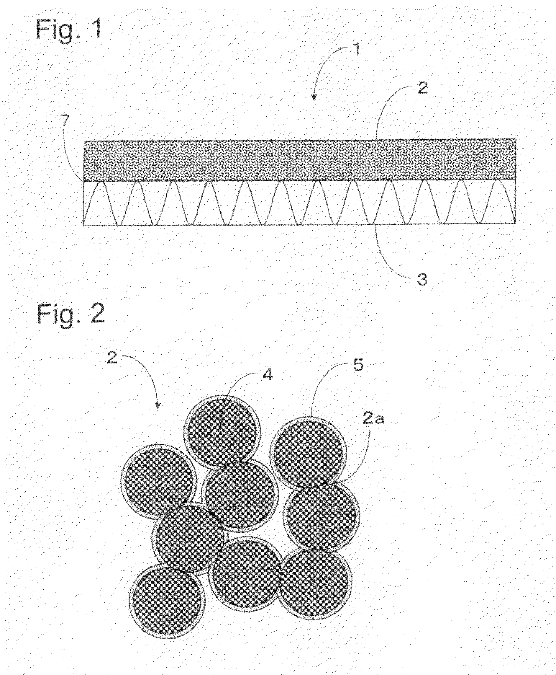
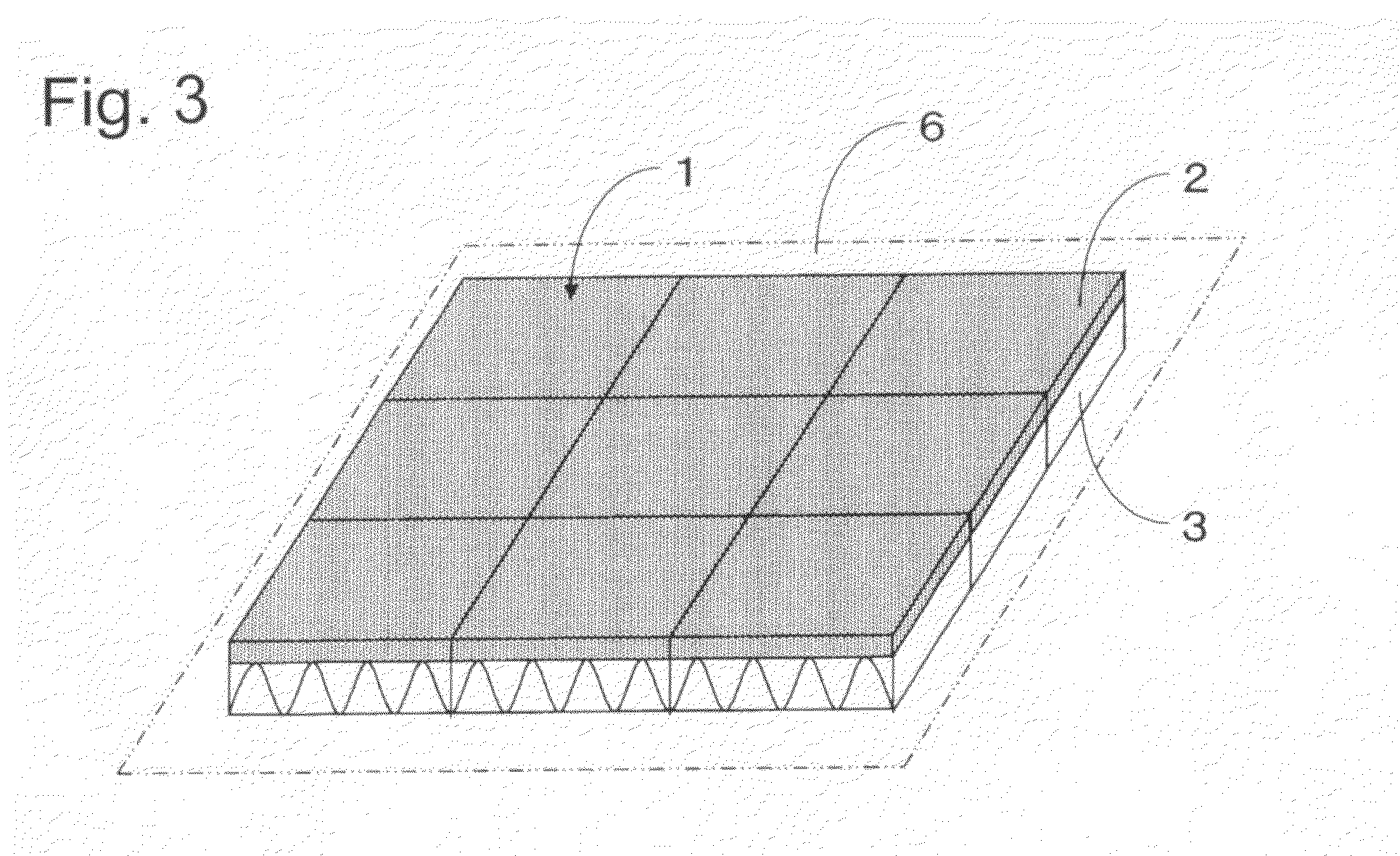
[0055]The strength necessary for the surface layer 2 refers to the strength which enables light walking on the upper surface of the surface layer 2 when the exterior heat insulation panel 1 is placed on a floor. Specifically, the strength refers to the strength at which breaking does not occur in the falling ball test and the bending test described later in Embodiment 3 and the strength greater than a standard of 150 N.

[0056]It is preferable for the surface layer 2 to have a specific gravity of 0.4 to 1.2, and the reason is as follows. If the specific gravity of the surface layer 2 is smaller than 0.4, the tread pressure resistance becomes extremely poor, and thus breaking and defects occur on the surface layer 2 due to the collapse of the porous aggregate. Also, if the specific gravity of the surface layer 2 exceeds 1.2, not only is the water retention rate of the surface layer 2 extremely deteriorated, but also the water permeability of the surface layer 2 becomes extremely poor. ...

embodiment 1

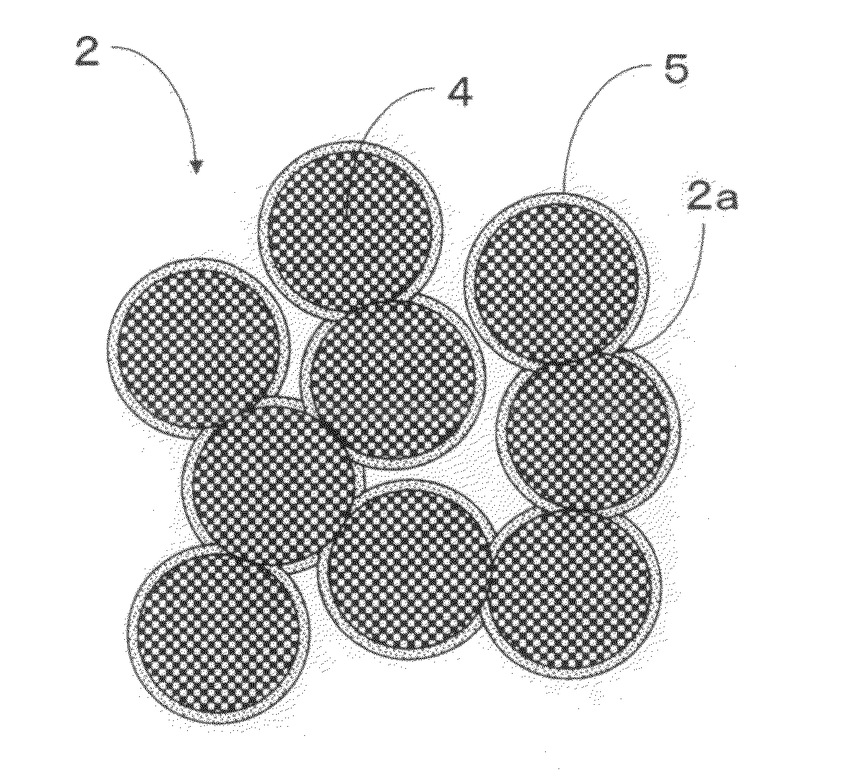
[0065]It is necessary for the binding component to function to fix the porous aggregate 4. It is also necessary for the binding component to include such material and structure that the binding component can maintain its structure even when a load is applied to the exterior heat insulation panel 1. In addition, it is preferable that the binding component does not require, particularly, heating and calcination during manufacturing the panel, is excellent in hydrophilicity, water resistance, heat resistance, ultraviolet degradation resistance, and strength, and can be cured at normal temperature. Accordingly, the cement 5 is used as the binding component in the Also, in the invention, the porous aggregate 4 is coated with the cement 5 and fixed through the contact portion 2.

[0066]The exterior heat insulation panel 1 including such a structure has strong pressure resistance due to the skeletal structure of the porous aggregate 4. As described later, it is necessary for the exterior he...


PUM


Abstract

An exterior heat insulation panel is disclosed which uses vaporization heat of water. The exterior heat insulation panel is installed on the surface of a roof or walls of a structure and is used for cooling and air-conditioning of structures, particularly, to an exterior heat insulation panel which can achieve high efficiency and energy-saving. The exterior heat insulation panel includes a surface layer having a continuous capillary tube structure and a non-capillary tube void structure made of porous aggregate combined by a hydrophilic binding component, and a foamed organic resin type of heat-retaining board having closed pores. The heat-retaining board and the surface layer are integrated by compression molding.

Description

BACKGROUND OF THE INVENTION[0001]1. Field of the Invention[0002]The present invention relates to an exterior heat insulation panel which uses vaporization heat of water and is used for cooling and air-conditioning of structures, particularly, to an exterior heat insulation panel which can achieve high efficiency and energy-saving.[0003]2. Description of Related Art[0004]Recently, global warming and urban heat islands due to excessive use of fossil fuels have become urgent issues to be resolved. In this context, in order to deal with the issue, various new energies and energy saving systems have been proposed so far.[0005]The roof, walls, and the like of a building readily reach a high temperature during daytime since they are exposed to direct sunlight for a long time. Particularly, during the summer when solar radiation hours are long, the heat absorbed from the surface of a roof and walls is transferred to inside the structure, thereby elevating the room temperature. The heat tran...

Claims


Application Information

Patent Timeline
Patent Type & Authority Applications(United States)
IPC IPC(8): E04B1/76
CPCB32B5/22Y02B30/545Y10T428/24157E04B1/7654E04D13/1662F24F5/0035Y10T428/249967Y10T428/249956Y10T428/249969Y10T428/24998Y10T428/249975Y10T428/249953Y02B30/54
Inventor TSUNEMORI, ITSUKINAGAHASHI, KAZUO
Owner KAISUI CHEM IND CO LTD
Learn More