Microfluidic systems incorporating flow-through membranes

a technology of flow-through membranes and microfluidic systems, which is applied in the direction of instruments, suspensions and porous materials analysis, material analysis, etc., can solve the problems of limiting the control of assay conditions and not allowing individual control of binding reactions, and achieves rapid, accurate and controlled manners

Inactive Publication Date: 2011-06-23
UNIV OF WASHINGTON
View PDF17 Cites 37 Cited by
  • Summary
  • Abstract
  • Description
  • Claims
  • Application Information

AI Technical Summary

Benefits of technology

[0007]The invention provides an assay device and methods for detection of an analyte in a fluidic sample. The device comprises a microfluidic chamber having first and second channels. The first channel is defined by walls and a floor, the channel having an upstream end and a downstream end, wherein fluid brought into contact with the channel flows from the upstream end toward the downstream. The floor comprises a region between the upstream and downstream ends that contains a porous membrane having an upper surface and a lower surface.

Problems solved by technology

The dependence on wicking to generate flow greatly limits the control over assay conditions.
This premixing leads to false negatives at high analyte concentrations (th

Method used


Image

  • Microfluidic systems incorporating flow-through membranes
  • Microfluidic systems incorporating flow-through membranes
  • Microfluidic systems incorporating flow-through membranes

Examples


example 1

Venting Air Away from Assay Membrane

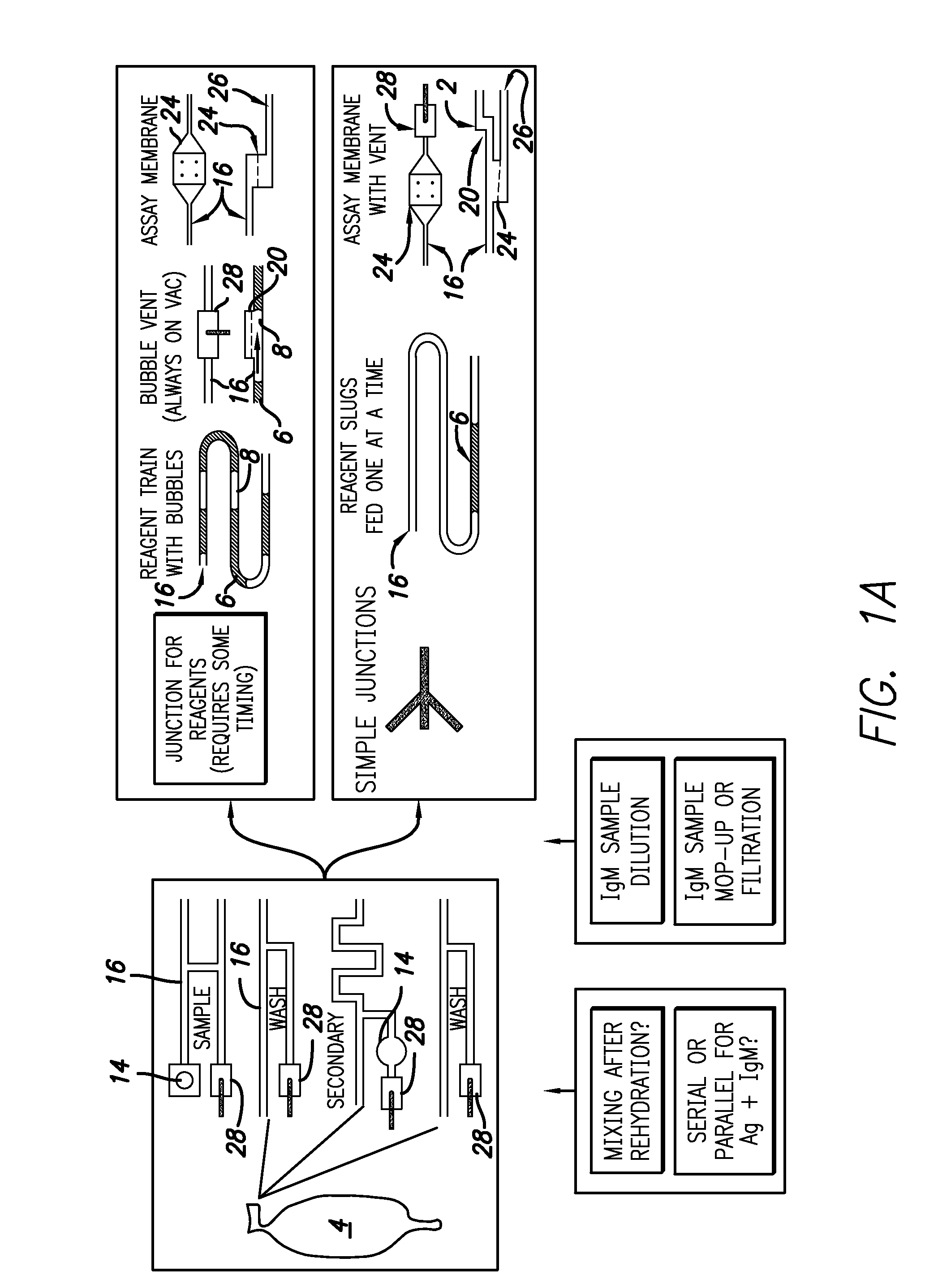
[0050]Three approaches to venting air away from the assay membrane to facilitate regulated fluid flow across the membrane are summarized. One approach involves diverting air between fluids to a channel upstream of the assay membrane. This approach is described in greater detail in Example 5 below entitled “Enabling a microfluidic immunoassay for the developing world by integration of on-card dry-reagent storage”. See also “Air removal by waste channel upstream of the assay membrane” appended to this document. A second approach relates to venting air between fluids through a hydrophobic membrane upstream of the assay membrane, and a third to venting trapped air through a hydrophobic membrane downstream of the assay membrane.

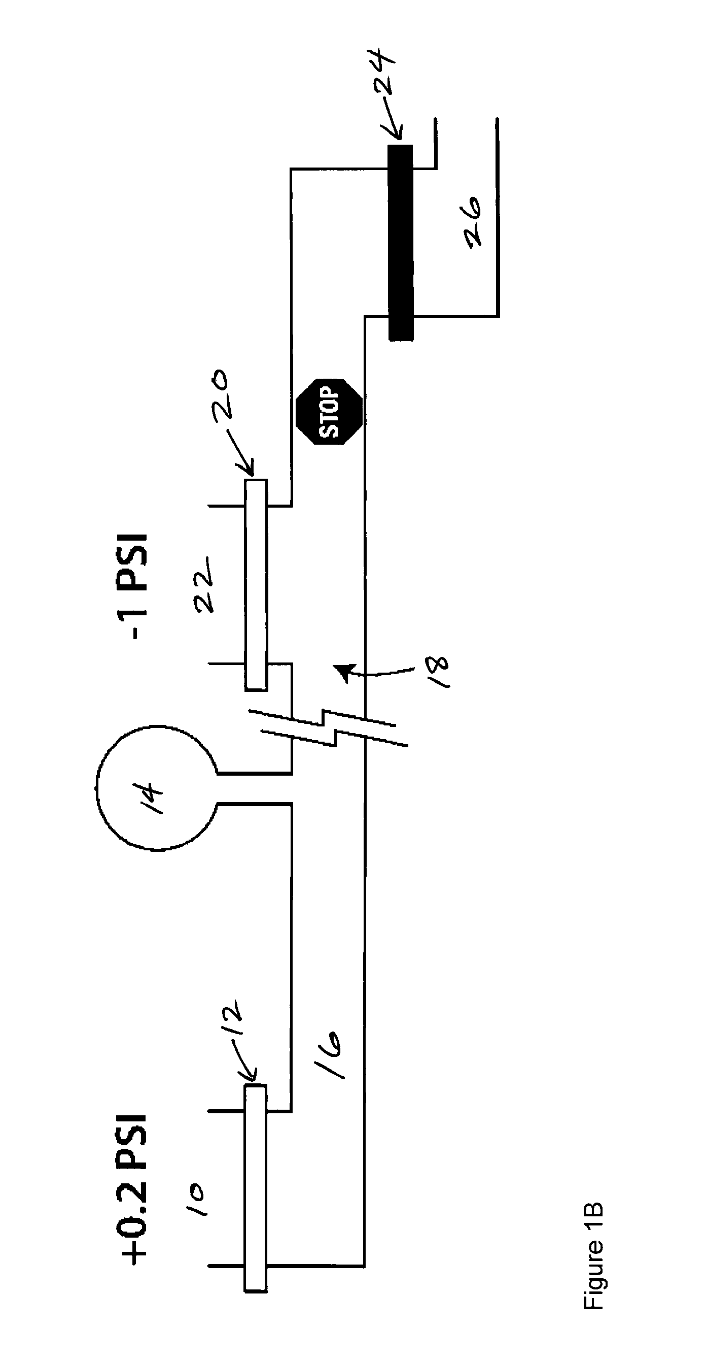
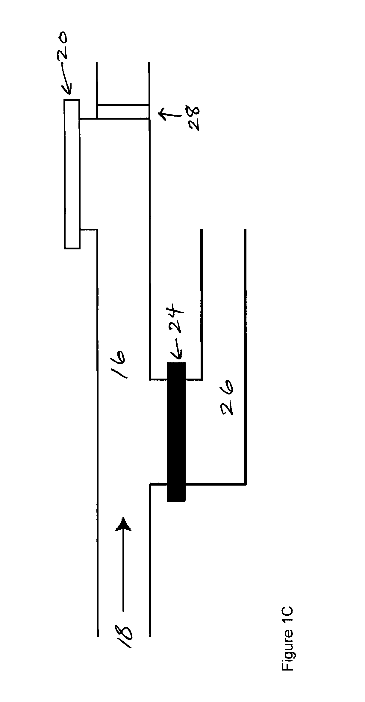
[0051]A general description of a card design for flow-through-membrane assay is illustrated in FIG. 1A. Individual fluids delivered to the membrane are likely to be separated from one another by air. Since the air cannot pass th...

example 2

Enabling a Microfluidic Immunoassay for the Developing World by Integration of on-Card Dry-Reagent Storage

[0057]This example describes a microfluidic flow-through membrane immunoassay with on-card dry reagent storage. By preserving reagent function, the storage and reconstitution of anhydrous reagents enables the devices to remain viable in challenging, unregulated environmental conditions. The assay takes place on a disposable laminate card containing both a porous membrane patterned with capture molecules and a fibrous pad containing an anhydrous analyte label. To conduct the assay, the card is placed in an external pumping and imaging instrument capable of delivering sample and rehydrated reagent to the assay membrane at controlled flow rates to generate quantitative results. Using the malarial antigen Plasmodium falciparum histidine-rich protein II (PfHRP2) as a model, this example demonstrates selection of dry storage conditions, characterization of reagent rehydration, and exe...

example 3

Rapid Air-Driven Point-of-Care Malaria Detection

[0127]This example demonstrates pneumatically actuated microfluidic cards that provide an inexpensive multiplexable platform for the point-of-care (POC) detection of disease, exemplified here for malaria (P. falciparum), in under nine minutes. Reagent volumes are metered and sequentially driven through a porous membrane used as a flow-through substrate for a sandwich immunoassay (SIA). An initial test of 500 ng / mL PfHRPII spiked into human plasma produced signal intensity six times greater than the local background. This successful test demonstrates the conversion of a multi-step benchtop immunoassay into a fully-automated microfluidic format while retaining the potential to be quantitative.

[0128]These microfluidic cards use a novel flow-through membrane format controlled by a fully automated, pneumatically driven system. The SIA is performed on the surface of a porous membrane that the reagents flow through. The small pores decrease d...


PUM


Abstract

Disclosed is a flow-through membrane assay that takes advantage of a high surface area and rapid transport while allowing individual control over flow rates and times for each step of a multi-step assay. A microfluidic card features channels in communication with a porous membrane, channels on either side of membrane to allow transverse flow across the membrane, capturing a labeled target from the sample by flowing the sample across the membrane, or capturing a target from the sample followed by flowing a reagent containing a label that binds to the target. Fluid can be pushed or pulled through the assay membrane by external control. Air near the membrane is managed by diverting air between fluids to a channel upstream of the assay membrane, venting air between fluids through a hydrophobic membrane upstream of the assay membrane, and/or by venting trapped air through a hydrophobic membrane downstream of the assay membrane.

Description

[0001]This application claims benefit of U.S. provisional patent application No. 61 / 091,639, filed Aug. 25, 2008, the entire contents of which are incorporated herein by reference. This application is related to PCT application number US07 / 80479, filed Oct. 4, 2007, the entire contents of which are incorporated herein by reference.TECHNICAL FIELD OF THE INVENTION[0002]This invention relates generally to methods and devices using porous flow-through membranes in molecular affinity assays performed in a microfluidic environment. The invention relates to use of such membranes for a variety of operations, including filtering, solid-phase assay and selective capture.BACKGROUND OF THE INVENTION[0003]Immunoassays take advantage of the specific binding abilities of antibodies to be widely used in selective and sensitive measurement of small and large molecular analytes in complex samples. The driving force behind developing new immunological assays is the constant need for simpler, more rap...

Claims


Application Information

Patent Timeline
IPC IPC(8): G01N33/53G01N33/48G01N30/00G01N1/00
CPCY10T436/25G01N33/54366
Inventor STEVENS, DEAN Y.LAFLEUR, LISA K.LUTZ, BERRY R.SPICAR-MIHALIC, PAOLOYAGER, PAUL
Owner UNIV OF WASHINGTON
Why Eureka
Try Eureka