Process and apparatus for vapor phase purification during hydrochlorination of multi-hydroxylated aliphatic hydrocarbon compounds

a technology of aliphatic hydrocarbons and purification methods, which is applied in the direction of sustainable manufacturing/processing, azeotropic distillation, separation processes, etc., can solve the problems of increasing the loss of hcl in the tailgas and not addressing the increase in hcl in the reaction mixtur

Inactive Publication Date: 2011-06-23
BLUE CUBE IP
View PDF10 Cites 11 Cited by
  • Summary
  • Abstract
  • Description
  • Claims
  • Application Information

AI Technical Summary

Problems solved by technology

CN 101007751A, however, does not address the increased loss of HCl from the reaction mixture resulting from this proc...

Method used


Image

  • Process and apparatus for vapor phase purification during hydrochlorination of multi-hydroxylated aliphatic hydrocarbon compounds
  • Process and apparatus for vapor phase purification during hydrochlorination of multi-hydroxylated aliphatic hydrocarbon compounds
  • Process and apparatus for vapor phase purification during hydrochlorination of multi-hydroxylated aliphatic hydrocarbon compounds

Examples


example 1

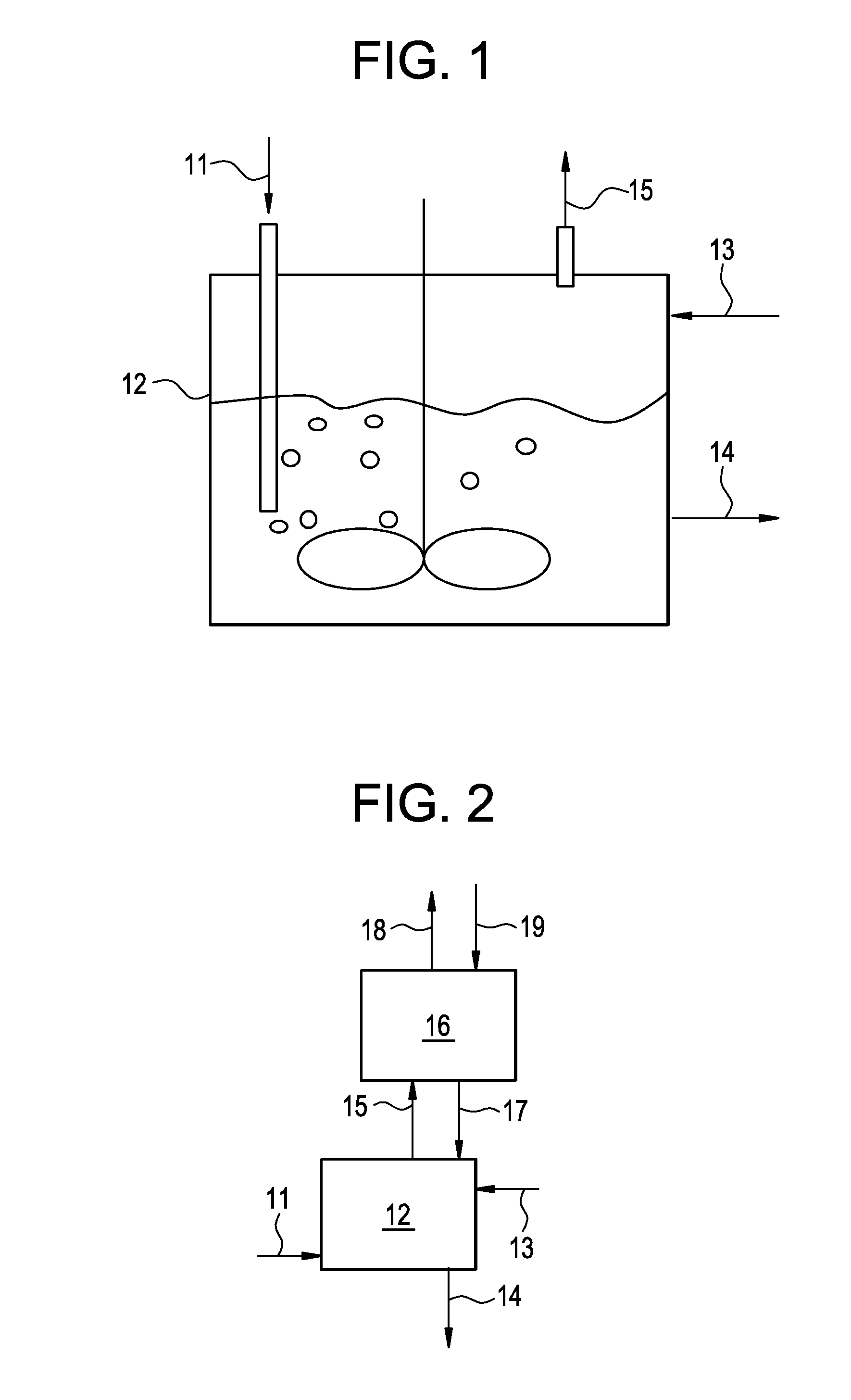
[0130]This example illustrates a process conducted according to the present invention shown in FIG. 2. This example was produced by simulating the present invention using commercially available software and proprietary physical properties, thermodynamics and kinetic models of the major components.

[0131]The reactor (12) was simulated as CSTR reactor at 15 bar pressure and 105° C. temperature. The absorber (16) was simulated as falling film absorber operating at 100° C. temperature and 11 bar pressure. The results of the simulation are presented below in Table 1.

TABLE 1Stream11131415171819Mass Flow kg / hr4093170015133927521886588717000Mass FractionINERTS0.0540.1000.0880.0910.8170.100HCl0.9450.0000.0900.7100.0950.1820.000Other Mixed0.0000.0000.8990.0200.0030.0000.000ChlorohydrinesABSORBENT0.0000.9000.0100.0000.8110.0000.900

example 2

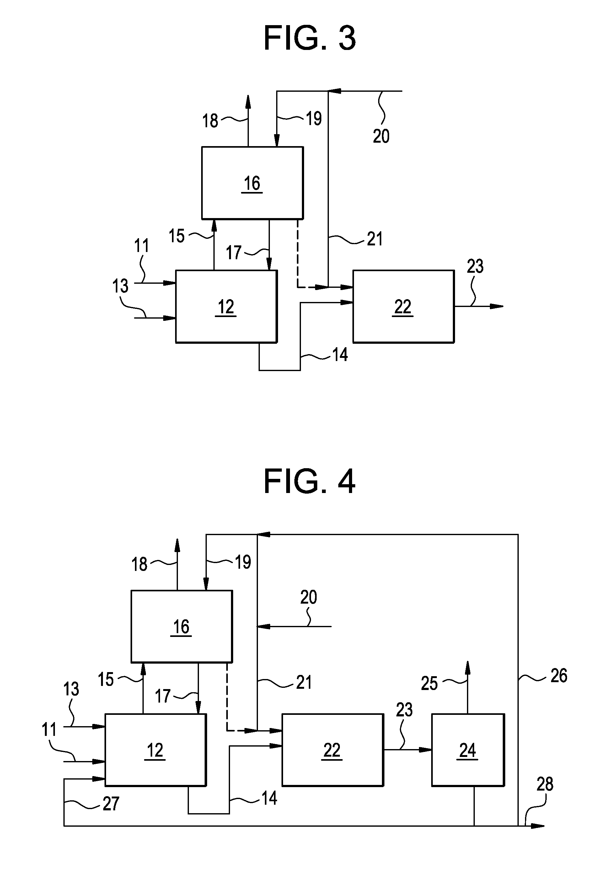
[0132]This example illustrates a process conducted according to the present invention as shown in FIG. 3. This example was produced by simulating the present invention using commercially available software and proprietary physical properties, thermodynamics and kinetic models of the major components.

[0133]The reactor (12) was simulated as CSTR reactor at 15 bar pressure and 110° C. temperature. The absorber (16) was simulated as absorber operating at 8.5 bar pressure having 3 theoretical stages. The reactor (22) was simulated as an adiabatic plug flow reactor operating at 10 bar pressure. The results of the simulation are presented below in Table 2.

TABLE 2Stream11131415171819202123Total Flow kg / hr4094936151327623107271115935017001765069704Mass FractionINERTS0.05500.00000.08830.36250.08790.80320.10000.10000.10000.1099HCl0.94500.00010.08990.61340.12200.19680.00000.00000.00000.0459Other Mixed0.00000.78190.90040.02940.09340.00540.10000.10000.10000.8362ChlorohydrinsABSORBENT0.00000.21800...

example 3

[0134]This example illustrates a process conducted according to the present invention as shown in FIG. 4. This example was produced by simulating the invention using commercially available software and proprietary physical properties, thermodynamics and kinetic models of the major components.

[0135]The reactor (12) was simulated as CSTR reactor at 9 bar pressure and 105° C. temperature. The absorber (16) was simulated as absorber operating at 8.5 bar pressure having 3 theoretical stages. The reactor (22) was simulated as an adiabatic plug flow reactor operating at 10 bar pressure. The separation device (24) was simulated as a distillation column operating at pressure 0.07 bar, having 15 theoretical stages with the feed at stage 9. The distillate to reflux ratio was set as 15:1. The boil up ratio in the column was set as 1.55. The results of the simulation are presented below in Table 3.

TABLE 3Stream1113141517Total Flow kg / hr394311295549981375045165Mass FractionINERTS0.05500.00100.088...


PUM

PropertyMeasurementUnit
Fractionaaaaaaaaaa
Fractionaaaaaaaaaa
Timeaaaaaaaaaa

Abstract

A process for converting multihydroxylated-aliphatic hydrocarbon compound(s) and/or ester(s) thereof to chlorohydrins and/or esters thereof is disclosed in which one or more of multihydroxylated-aliphatic hydrocarbon compound(s) and/or ester(s) thereof and/or monochlorohydrin(s) and/or ester(s) thereof with at least one chlorinating feed stream comprising at least one chlorinating agent and at least one impurity having a boiling point below the boiling point of the chlorohydrin product having the lowest boiling under hydrochlorination conditions, optionally in the presence of water, one or more catalyst(s), and/or one or more heavy byproduct(s) in a reaction vessel under hydrochlorination conditions, wherein the liquid-phase reaction mixture is maintained at a temperature below the boiling point of the chlorohydrin product having the lowest boiling point under hydrochlorination conditions and greater than the boiling point(s) of the at least one impurity and a vapor phase vent stream comprising the at least one impurity is removed from the liquid phase reaction mixture. An apparatus suitable for carrying out the disclosed process is illustrated in FIG. 1 of the drawings. The process and apparatus improve conversion rates and/or provide for recovery of chlorinating agent for lower operating costs.

Description

BACKGROUND OF THE INVENTION[0001]The present invention relates to processes and apparatus for converting multihydroxylated-aliphatic hydrocarbon compound(s) and / or ester(s) thereof to chlorohydrins and / or esters thereof.[0002]Dichlorohydrins are useful for making epoxides such as epichlorohydrins. Epichlorohydrin is a widely used precursor to epoxy resins. Epichlorohydrin is a monomer which is commonly used for the alkylation of para-bisphenol A. The resultant diepoxide, either as a free monomer or oligomeric diepoxide, may be advanced to high molecular weight resins which are used for example in electrical laminates, can coatings, automotive topcoats and clearcoats.[0003]Glycerin is considered to be a low-cost, renewable feedstock that is a co-product of the biodiesel process for making fuel. It is known that other renewable feedstocks such as fructose, glucose and sorbitol can be hydrogenolized to produce mixtures of vicinal diols and triols, such as glycerin, ethylene glycol, 1,2...

Claims


Application Information

Patent Timeline
IPC IPC(8): C07C31/34B01J8/00
CPCB01D3/14B01D3/146B01D3/36B01D3/38C07C29/62C07C31/42Y02P20/10C07C29/82C07C31/36
Inventor HOOK, BRUCE D.FORLIN, ANNAMERENOV, ANDREI S.TIRTOWIDJOLO, DANILMEHTA, ANIL J.VERWIJS, JAN W.VERWIJS-VAN DEN BRINK, AALTJEVERWIJS, LENAVERWIJS, HENDRIKA GERRITAHENSEN, WILMA
Owner BLUE CUBE IP
Why Eureka
Try Eureka