
Check matrix creation device, check matrix creation method, check matrix creation program, transmitter, receiver, and communication system

a technology of matrix creation and creation method, applied in the field of encoding technology for use in digital communications, can solve the problems of increasing the degree of complexity at the time of implementation, taking a long time to design an ldpc code,

Inactive Publication Date: 2011-06-23
MITSUBISHI ELECTRIC CORP
View PDF22 Cites 13 Cited by
  • Summary
  • Abstract
  • Description
  • Claims
  • Application Information

AI Technical Summary

Benefits of technology

[0030]The present invention is made in order to solve the above-mentioned problems, and it is therefore an object of the present invention to provide a check matrix creation device, a check matrix creation method, and a check matrix creation program capable of creating a parity-check matrix for an irregular LDPC code which has a better performance than that created using a method of configuring a check matrix through a computer search, and which has a regular configuration and can support a wide range of coding rates.
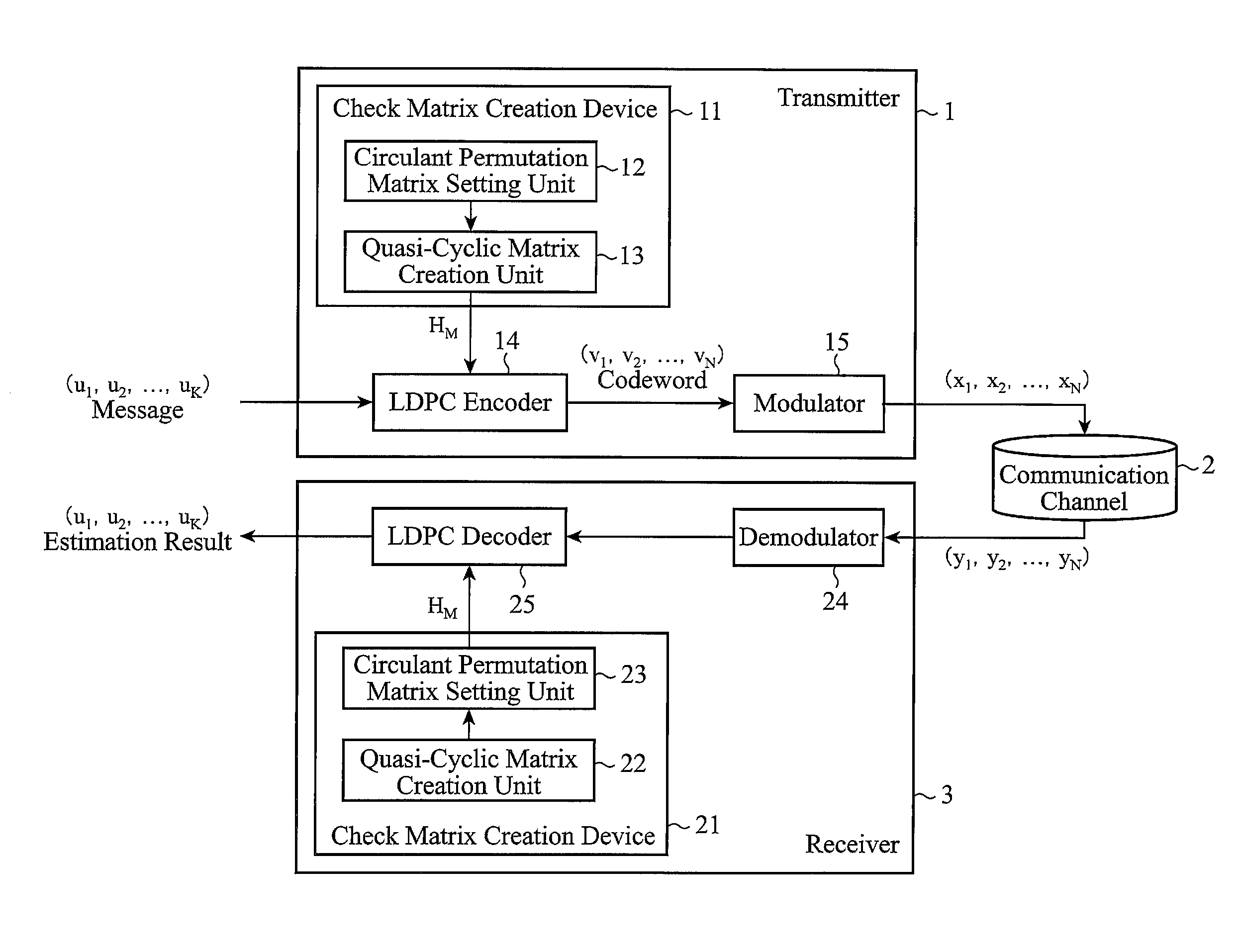
[0031]It is another object of the present invention to provide a transmitter and a communication system which have a good performance and which can encode predetermined information bits by using a parity-check matrix having a regular configuration, and transmit them.
[0032]It is a further object of the present invention to provide a receiver and a communication system which have a good performance and which can decode predetermined information bits by using a parity-check matrix having a regular configuration.
[0034]Because the check matrix creation device in accordance with the present invention is constructed in such a way as to include the circulant permutation matrix setting means for preparing a plurality of circulant permutation matrices, and the quasi-cyclic matrix creation means for arranging the plurality of circulant permutation matrices prepared by the circulant permutation matrix setting means both in the row direction and in the column direction to create a quasi-cyclic matrix, there is provided an advantage of being able to create a parity-check matrix for an irregular LDPC code which has a better performance than that created using a method of forming a check matrix through a computer search, and which has a regular configuration and can support a wide range of coding rates.

Problems solved by technology

A problem is therefore that it is necessary to design an LDPC code by mainly using a computer search and therefore it takes much time to design an LDPC code.
Another problem is that because such a method lacks in extendibility and also lacks in the regularity among circulant permutation matrices, the degree of complexity increases at the time of implementation.

Method used


Image

  • Check matrix creation device, check matrix creation method, check matrix creation program, transmitter, receiver, and communication system
  • Check matrix creation device, check matrix creation method, check matrix creation program, transmitter, receiver, and communication system
  • Check matrix creation device, check matrix creation method, check matrix creation program, transmitter, receiver, and communication system

Examples


embodiment 2

[0136]FIG. 12 is a block diagram showing a communication system in accordance with Embodiment 2 of the present invention.

[0137]In above-mentioned Embodiment 1, the example in which the communication device on the transmit side is the transmitter 1 and the communication device on the receive side is the receiver 3 is shown (refer to FIG. 1). In contrast, in this Embodiment 2, an example in which a mobile terminal 100 and a base station 200 transmit and receive data to and from each other is shown.

[0138]In the figure, a physical layer LDPC encoder 101 of the mobile terminal 100 is applied to a fading communication channel or the like in a physical layer, and constructs the LDPC encoder 14 of FIG. 1. Furthermore, the physical layer LDPC encoder 101 can include the check matrix creation device 11 of FIG. 1, or the check matrix creation device 11 of FIG. 1 can be disposed separately from the physical layer LDPC encoder 101.

[0139]A modulator 102 of the mobile terminal 100 carries out a pr...

embodiment 3

[0159]FIG. 13 is a block diagram showing a communication system in accordance with Embodiment 3 of the present invention.

[0160]In above-mentioned Embodiment 1, the example in which the communication device on the transmit side is the transmitter 1 and the communication device on the receive side is the receiver 3 is shown (refer to FIG. 1). In contrast, in this Embodiment 3, an example in which a mobile terminal 300 and a base station 400 transmit and receive data to and from each other is shown.

[0161]In the figure, an upper hierarchical layer LDPC encoder 301 of the mobile terminal 300 is applied to a correction or the like in an upper hierarchical layer of a packet error occurring in a fading communication channel or the like, and constructs the LDPC encoder 14 of FIG. 1. Furthermore, the upper hierarchical layer LDPC encoder 301 can include the check matrix creation device 11 of FIG. 1, or the check matrix creation device 11 of FIG. 1 can be disposed separately from the upper hie...

embodiment 4

[0181]In this Embodiment 4, a concrete example of the parity-check matrix is shown explicitly.

[0182]For example, the following check matrix HCH is the one of a code having a coding rate of ½ which is used by the International Standards IEEE802.16e. In the check matrix, each numeral shows pj,l, and “−1” shows a p×p zero matrix.

HCH=-19473-1-1-1-1-15583-1-170-1-1-1-1-1-1-1-1-1-1-127-1-1-122799-1-1-112-100-1-1-1-1-1-1-1-1-1-1-1-1242281-133-1-1-10-1-100-1-1-1-1-1-1-1-161-147-1-1-1-1-16525-1-1-1-1-100-1-1-1-1-1-1-1-1-139-1-1-184-1-14172-1-1-1-1-100-1-1-1-1-1-1-1-1-1-14640-182-1-1-1790-1-1-1-100-1-1-1-1-1-1-19553-1-1-1-1-11418-1-1-1-1-1-1-100-1-1-1-1-11173-1-1-12-1-147-1-1-1-1-1-1-1-1-100-1-1-112-1-1-18324-143-1-1-151-1-1-1-1-1-1-1-100-1-1-1-1-1-1-194-159-1-17072-1-1-1-1-1-1-1-1-100-1-1-1765-1-1-1-13949-1-1-1-1-1-1-1-1-1-1-1-10043-1-1-1-166-141-1-1-1267-1-1-1-1-1-1-1-1-1-10

[0183]Next, an example of an extension of this check matrix HCH to create a check matrix having a coding rate of ⅓ is ...


PUM


Abstract

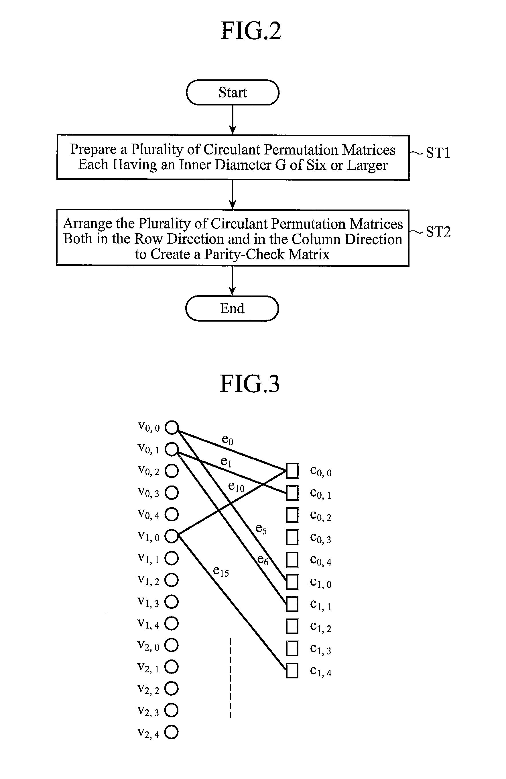
A check matrix creation device includes a circulant permutation matrix setting unit 12 for preparing a plurality of circulant permutation matrices each having an inner diameter of six or larger, and a quasi-cyclic matrix creation unit 13 for arranging the plurality of circulant permutation matrices prepared by the circulant permutation matrix setting unit 12 both in a row direction and in a column direction to create a quasi-cyclic matrix.

Description

FIELD OF THE INVENTION [0001]The present invention relates to an encoding technology for use in digital communications. More particularly, it relates to a check matrix creation device for, a check matrix creation method of and a check matrix creation program for creating a parity check matrix for an LDPC (Low-Density Parity Check) code, a transmitter that encodes predetermined information bits by using a parity check matrix for LDPC code and transmits the encoded predetermined information bits, a receiver that decodes predetermined information bits by using a parity check matrix for an LDPC code, and a communication system consisting of the above-mentioned transmitter and the above-mentioned receiver.BACKGROUND OF THE INVENTION[0002]Hereafter, a conventional communication system which uses an LDPC code as an encoding method will be explained.[0003]A case in which a quasi-cyclic (QC: Quasi-Cyclic) code is used as an example of an LDPC code will be explained (for example, refer to non...

Claims


Application Information

Patent Timeline
Patent Type & Authority Applications(United States)
IPC IPC(8): H03M13/11G06F11/10
CPCH03M13/1168H03M13/116
Inventor MATSUMOTO, WATARUYOSHIDA, HIDEO
Owner MITSUBISHI ELECTRIC CORP
Learn More