Dye for photoelectric conversion device and photoelectric conversion device
- Summary
- Abstract
- Description
- Claims
- Application Information
AI Technical Summary
Benefits of technology
Problems solved by technology
Method used
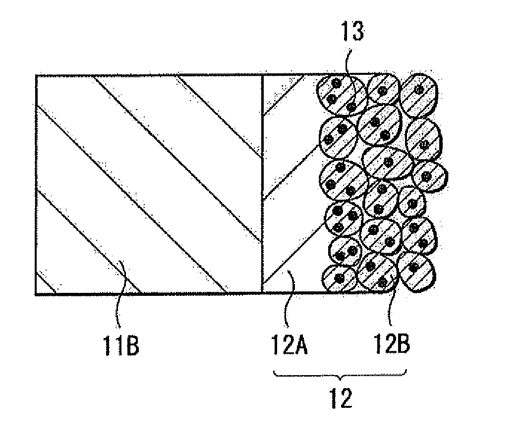
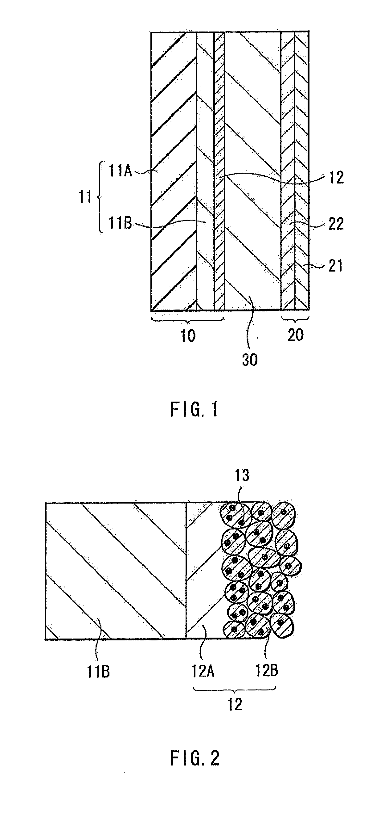
Image

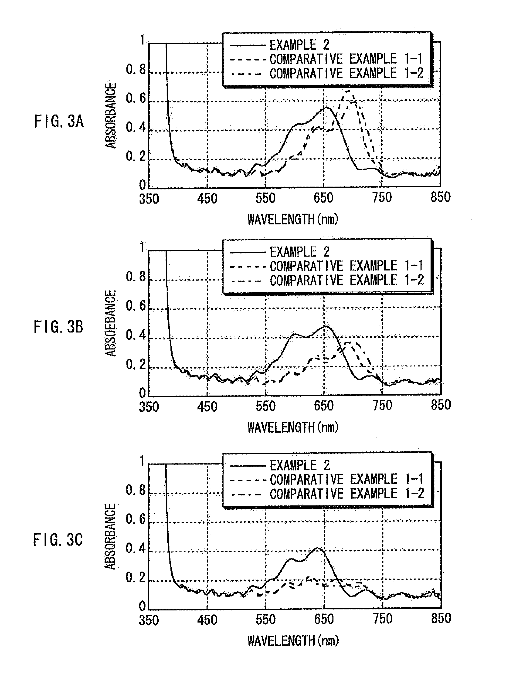
Examples
example 1-1
[0092]As a specific example of the dye explained in the foregoing embodiment, according to the foregoing Chemical formula (1) and the foregoing Chemical reaction formula (III), the compound shown in Chemical formula (7) as the compound shown in Chemical formula (4) was synthesized.
[0093]First, as shown in Chemical reaction formula (I-1), the compound expressed by Chemical formula (162-1) as the compound shown in Chemical formula (162) and the compound expressed by Chemical formula (163-1) as the compound shown in Chemical formula (163) were mixed and reacted. Thereby, the indolenium salt expressed by Chemical formula (164-1) as the quaternary ammonium salt expressed by Chemical formula (164) was obtained.
[0094]Next, as shown in Chemical reaction formula (III-1), the indolenium salt shown in Chemical formula (164-1) (10 mmol), amidine expressed by Chemical formula (167-5) as a bridge agent (5 mmol), acetic anhydride (20 mmol), triethylamine as a base (10 mmol), and acetonitrile (CH3C...
example 1-2
[0095]The compound shown in Chemical formula (8) was synthesized. First, as shown in Chemical reaction formula (I-2), the indolenium salt expressed by Chemical formula (164-2) was obtained in the same manner as that of Example 1-1, except that the compound expressed by Chemical formula (162-2) was used instead of the compound shown in Chemical formula (162-1). Next, a final product was obtained in the same manner as that of Example 1-1, except that the indolenium salt shown in Chemical formula (164-2) was used instead of the indolenium salt shown in Chemical formula (164-1). In this case, the yield was 50%.
example 1-3
[0096]The compound shown in Chemical formula (9) was synthesized. First, as shown in Chemical reaction formula (I-3), the indolenium salt expressed by Chemical formula (164-3) was obtained in the same manner as that of Example 1-1, except that the compound expressed by Chemical formula (162-3) was used instead of the compound shown in Chemical formula (162-1), and the compound expressed by Chemical formula (163-2) was used instead of the compound shown in Chemical formula (163-1). Next, a final product was obtained in the same manner as that of Example 1-1, except that the indolenium salt shown in Chemical formula (164-3) was used instead of the indolenium salt shown in Chemical formula (164-1). In this case, the yield was 2.3%.
PUM
 Abstract
Description
Claims
Application Information
 - R&D Engineer
- R&D Manager
- IP Professional
- Industry Leading Data Capabilities
- Powerful AI technology
- Patent DNA Extraction
Browse by: Latest US Patents, China's latest patents, Technical Efficacy Thesaurus, Application Domain, Technology Topic.
© 2024 PatSnap. All rights reserved.Legal|Privacy policy|Modern Slavery Act Transparency Statement|Sitemap