
Multiple Walled Primary Package with Phase Change Material

a phase change material and primary package technology, applied in the field of primary packages, receptacles or containers, can solve the problems of reducing the efficacy of compounds, reducing the work efficiency of workers, and reducing the cost of refrigeration, so as to improve the work efficiency, and improve the effect of work efficiency

Inactive Publication Date: 2011-06-30
ENTROPY SOLUTIONS
View PDF13 Cites 48 Cited by
  • Summary
  • Abstract
  • Description
  • Claims
  • Application Information

AI Technical Summary

Benefits of technology

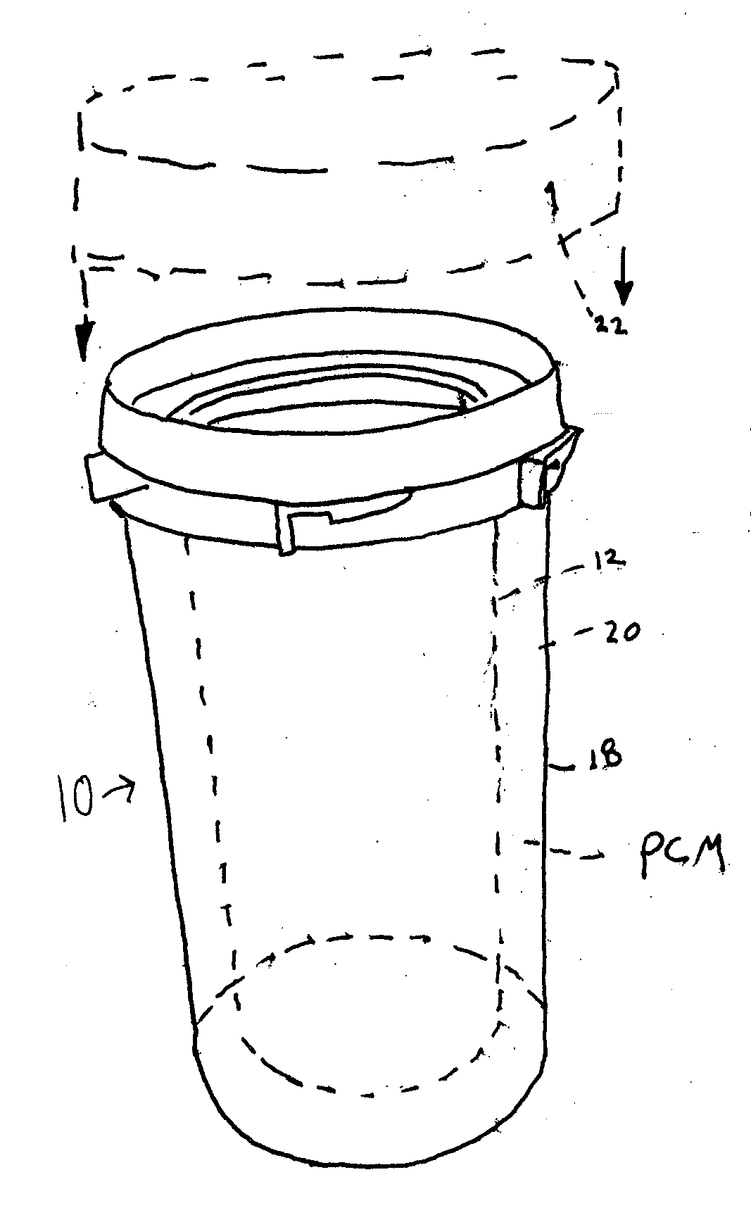
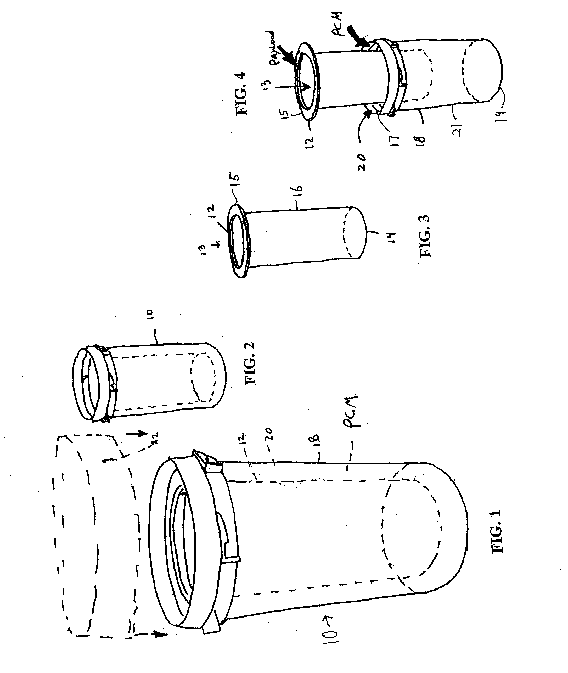
[0017]When an embodiment of the present invention includes two PCMs, a temperature sensitive compound may be maintained between a minimum temperature and a maximum temperature. The first PCM may be selected because it has a first phase change temperature sufficiently above the minimum temperature in the range to ensure the payload does not fall below the minimum temperature in the range, and a second PCM may be selected because it has a second phase change temperature sufficiently below the maximum temperature in the range to ensure the payload does not rise above the maximum temperature in the range. In one embodiment, the first PCM exists as a liquid within the target temperature range, and the second PCM as a solid. The first PCM changes from its liquid phase to its solid phase at a temperature sufficiently above the minimum temperature in the range to ensure the payload does not fall below the minimum temperature in the range, and the second PCM changes from its solid phase to its liquid phase at a temperature sufficiently below the maximum temperature in the range to ensure the payload does not rise above the maximum temperature in the range. In this manner, the latent heats associated with the respective phase changes assist in maintaining the temperature of the payload within the range. Virtually any desired target temperature range may be accommodated by appropriate selection of the first and second PCMs.
[0019]Implementations of the present invention may include none, one or more of the following advantages. Renewable PCMs (RPCMs) may be used in some embodiments of the present invention. RPCMs may be more environmentally friendly than traditional PCMs. RPCMs are typically non-toxic to animals, including human beings. Because RPCMs are typically non-toxic, the RPCMs may be a source of food. RPCMs can be biodegradable and non-carcinogenic. RPCMs may be safer to work with. The temperature of the phase transition of an RPCM may be easier to control than the phase transition temperature of a traditional PCM. An RPCM with a relatively high phase change temperature may be capable of absorbing or radiating more heat energy than a traditional PCM with a similar phase change temperature. An RPCM may be charged, i.e., cooled or heated, more quickly than a traditional PCM. An RPCM may have a longer working lifespan per gram weight as compared to a traditional PCM. RPCMs can be safe to microwave. Manufacture and disposal of the RPCM can be simpler than that of a traditional PCM. The raw materials for RPCMs are readily available from agricultural sources.

Problems solved by technology

While reasonably effective for keeping the compounds cool, refrigeration remains expensive and generally non-portable.
Loss of pharma-compounds or decreased efficacy of the compounds often results when the pharma-compound temperature exceeds a predetermined upper limit.

Method used


Image

  • Multiple Walled Primary Package with Phase Change Material
  • Multiple Walled Primary Package with Phase Change Material
  • Multiple Walled Primary Package with Phase Change Material

Examples


second embodiment

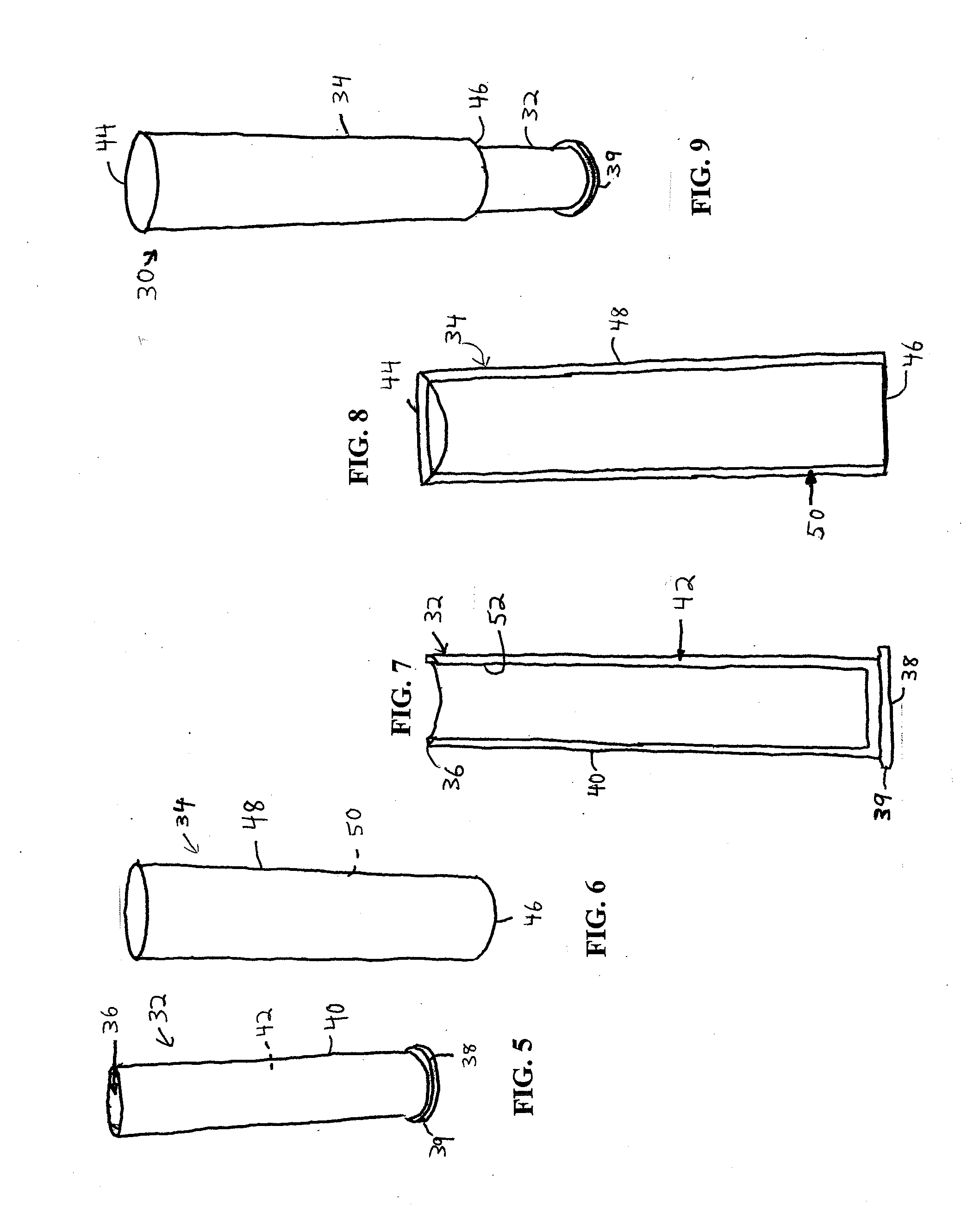
[0042]FIGS. 5-9 depict a container of the present invention. In this embodiment, two double-walled vessels, an inner vessel 32 and an outer shell 34, contain PCM. These two double-walled vessels together form container 30. FIG. 5 shows a perspective view, and FIG. 7 shows a cross-sectional view, of inner vessel 32. Inner vessel 32 includes an open upper end 36 and a closed lower end 38 connected by a hollow inner vessel wall 40. A rim 39 extends around the closed lower end 38. A PCM 42 is contained within the hollow inner vessel wall 40. Closed lower end 38 may also be comprised of a hollow panel containing a PCM.

[0043]FIG. 6 shows a perspective view, and FIG. 8 shows a cross-sectional view, of outer shell 34. Outer shell 34 includes a closed upper end 44 and an open lower end 46 connected by a hollow outer shell wall 48. A PCM 50 is contained within the hollow outer shell wall 48. Closed upper end 44 may also be comprised of a hollow panel containing a PCM. In this embodiment, PCM ...

third embodiment

[0048]FIGS. 10-12 depict a container of the present invention. FIG. 12 depicts the assembled container 60, while FIG. 11 depicts a disassembled container 60. Container 60 includes a syringe 62 and an outer sleeve 64. As shown in FIG. 10, syringe 62 includes barrel 66, plunger 68, and needle 70. As shown in FIG. 11, the outer sleeve 64 includes an open upper end 72 and an open lower end 74 connected by a hollow outer sleeve wall 76. PCM 78 is contained within the hollow outer sleeve wall 76.

[0049]In the assembled container 60, the outer sleeve 64 surrounds the syringe barrel 66, such that the hollow outer sleeve wall 76 is in direct contact with the syringe barrel 66. In the embodiment shown in FIGS. 10-12, both ends of the outer sleeve 64 are open, enabling the syringe 62 to be used while contained within the outer sleeve 64. However, in other embodiments, the outer sleeve 64 may include a closed end. If the outer sleeve 64 includes a closed end, the syringe barrel 66 can be stored ...


PUM


Abstract

A container for a temperature sensitive product, such as a pharmaceutical compound, includes an inner vessel and an outer shell. When the inner vessel is contained in the outer shell, a chamber adapted to receive a phase change material is defined between an inner vessel wall and an outer shell wall. A container may also include multiple chambers defined by multiple walls, with different phase change materials disposed in different chambers. A cap, such as a child-proof cap, may be used to secure the contents of the container.

Description

RELATED APPLICATIONS[0001]This application claims the benefit of U.S. Provisional Application No. 61 / 291,707 filed Dec. 31, 2009, and incorporated herein by reference.FIELD OF THE INVENTION[0002]The subject invention relates generally to primary packages, receptacles or containers and more specifically to a receptacle that cools or heats a payload to a temperature range and then maintains the payload in a desired temperature range for an extended period.BACKGROUND OF THE INVENTION[0003]It is generally held as desirable to consume or administer certain pharmaceutical compounds (“pharma-compounds”), when they are cold, i.e., below a predetermined upper temperature. Refrigerating the compounds is the common way of maintaining a desired temperature range. While reasonably effective for keeping the compounds cool, refrigeration remains expensive and generally non-portable.[0004]In the absence of active refrigeration means, the consumer may rely on insulated containers to limit heat loss ...

Claims


Application Information

Patent Timeline
Patent Type & Authority Applications(United States)
IPC IPC(8): B65D85/00
CPCA61J1/165
Inventor LINDQUIST, ERICHAUN, LUKEWILLIAMS, PRESTON
Owner ENTROPY SOLUTIONS
Learn More