System and method for controlling deflection of a charged particle beam within a graded electrostatic lens

a technology of electrostatic lens and charged particle, which is applied in the direction of beam deviation/focusing by electric/magnetic means, printers, instruments, etc., can solve the problems of difficult to tune the ion beam, (may not be readily feasible, conventional systems and methods do not provide a solution for independent control of the deflection and/or focus of the ion beam, etc., and achieve small adjustment of the deflection angle

Active Publication Date: 2011-06-30
VARIAN SEMICON EQUIP ASSOC INC
View PDF4 Cites 31 Cited by
  • Summary
  • Abstract
  • Description
  • Claims
  • Application Information

AI Technical Summary

Benefits of technology

[0009]A method is disclosed for assigning electrode voltages within a decel/deflect lens which maintains an arcuate motion of the beam, matching the symmetry of the graded decel/deflect lens. Small adjustment of deflect angle is accomplished smoothly, via small adjustments of the voltages throughout lens, rather than abru...

Problems solved by technology

For example, the deceleration lens 200, which may provide co-local deflection for filtering energetic neutrals, may face challenges associated with control of deflection angle and beam focus.
This may lead to difficulty in tuning the ion beam 20 since tuning the size of the ion beam 20 (focus) may not be readily feasible if a position of the ion beam 2...

Method used


Image

  • System and method for controlling deflection of a charged particle beam within a graded electrostatic lens
  • System and method for controlling deflection of a charged particle beam within a graded electrostatic lens
  • System and method for controlling deflection of a charged particle beam within a graded electrostatic lens

Examples


Embodiment Construction

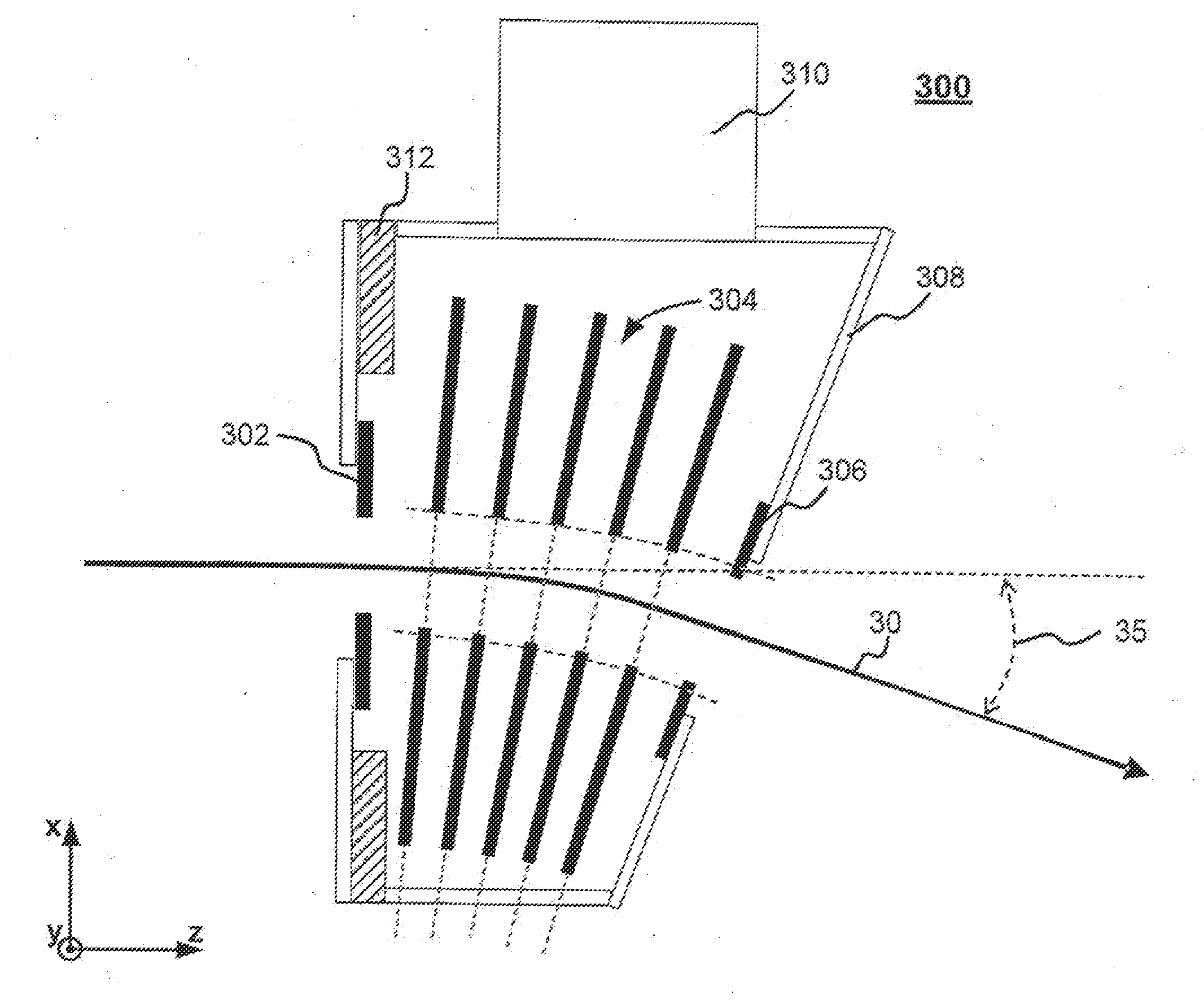
[0029]To solve the problems with conventional lens configurations, an improved electrostatic lens configuration may include one or more variable-control suppression / focusing electrodes. These electrodes may include a variety of shapes, curvatures, positions, materials, and / or configurations that are independently or separately controlled / biased with respect to one another thereby providing flexible and effective manipulation of an ion beam's shape as well as its energy.

[0030]FIG. 3 depicts a side view of an exemplary graded lens configuration 300. The graded lens configuration 300 may include several sets of electrodes. For example, the graded lens configuration may include a set of entrance electrodes 302, one or more sets of suppression / focusing electrodes 304, and a set of exit electrodes 306. Each set of electrodes may have a space / gap to allow an ion beam 30 (e.g., a ribbon beam) to pass therethrough.

[0031]In some embodiments, these electrodes (e.g., entrance electrode 302, sup...


PUM


Abstract

A method and apparatus for controlling deflection, deceleration, and focus of an ion beam are disclosed. The apparatus may include a graded deflection/deceleration lens including a plurality of upper and lower electrodes disposed on opposite sides of an ion beam, as well as a control system for adjusting the voltages applied to the electrodes. The difference in potential between pairs of upper and lower electrodes are varied using a set of “virtual knobs” that are operable to independently control deflection and deceleration of the ion beam. The virtual knobs include control of beam focus and residual energy contamination, control of upstream electron suppression, control of beam deflection, and fine tuning of the final deflection angle of the beam while constraining the beam's position at the exit of the lens. In one embodiment, this is done by fine tuning beam deflection while constraining the beam position at the exit of the VEEF. In another embodiment, this is done by fine tuning beam deflection while measuring the beam position and angle at the wafer plane. In a further embodiment, this is done by tuning a deflection factor to achieve a centered beam at the wafer plane.

Description

BACKGROUND OF THE INVENTION[0001]1. Field of the Invention[0002]Embodiments of the invention relate to the field of ion implantation for forming semiconductor structures. More particularly, the present invention relates to a method for controlling deflection of a charged particle beam within a graded electrostatic lens.[0003]2. Discussion of Related Art[0004]Ion implanters are widely used in semiconductor manufacturing to selectively alter conductivity of materials. In a typical ion implanter, ions generated from an ion source are directed through a series of beam-line components that may include one or more analyzing magnets and a plurality of electrodes. The analyzing magnets select desired ion species, filter out contaminant species and ions having undesirable energies, and adjust ion beam quality at a target wafer. Suitably shaped electrodes may modify the energy and the shape of an ion beam.[0005]FIG. 1 shows a conventional ion implanter 100 which comprises an ion source 102, e...

Claims


Application Information

Patent Timeline
IPC IPC(8): G21K1/06H01J3/14
CPCH01J37/1477H01J37/3171H01J2237/24514H01J2237/12H01J2237/053H01J37/12H01J37/1471H01J37/304
Inventor KELLERMAN, PETER L.SINCLAIR, FRANKBENVENISTE, VICTORLU, JUN
Owner VARIAN SEMICON EQUIP ASSOC INC
Why Eureka
Try Eureka