
Paste composition for solar cell, manufacturing method therefor and solar cell

a solar cell and composition technology, applied in the direction of non-conductive materials with dispersed conductive materials, conductors, metal/alloy conductors, etc., can solve the problems of external appearance that needs to be resolved, difficult to control such blemishes, and the warpage has not been resolved sufficiently to provide significant improvement in yield and line tact. , to achieve the effect of high conductivity

Inactive Publication Date: 2011-06-30
NORITAKE CO LTD
View PDF9 Cites 7 Cited by
  • Summary
  • Abstract
  • Description
  • Claims
  • Application Information

AI Technical Summary

Benefits of technology

The present invention provides a paste composition for forming a back electrode of a solar cell that can prevent warping of the substrate and suppress blemishes on the back electrode. The composition contains an aluminum powder, a glass powder, and a composite powder composed of a metal oxide and a silicon-containing organic or inorganic compound. The composite powder is included in an amount of at least 0.01 mass % but less than 0.45 mass % of the total composition. The use of this composite powder helps to control the warping of the substrate and improve the external appearance of the solar cell. The method for manufacturing the paste composition is also provided, which involves preparing the solids and mixing them with a liquid medium to prepare the paste. The use of a composite powder with the surface coated with a silicon-containing compound further enhances the effectiveness of the paste composition.

Problems solved by technology

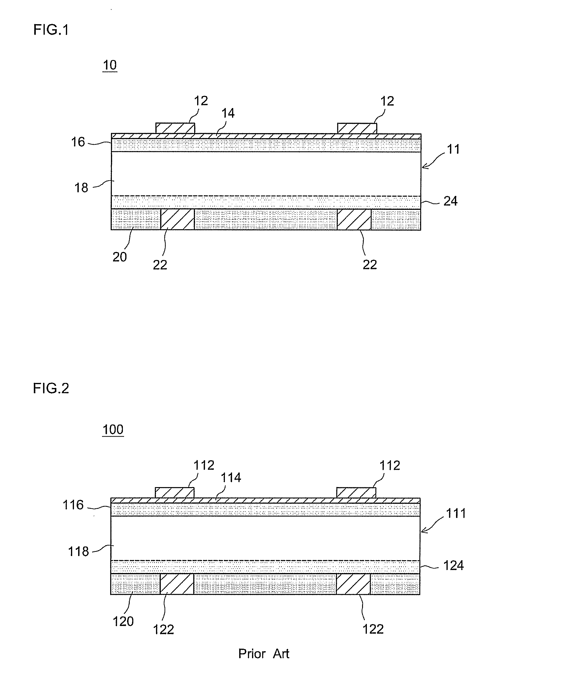
However, although some improvement in the aforementioned problems of prior art (that is, warpage and curling of the substrate during firing of the aluminum electrode) can be can be obtained by applying the techniques (aluminum-containing paste compositions) described in these patent documents, warpage has still not been resolved sufficiently to provide significant improvement in yields and line tact (for example, the warpage has not been reduced by ten times or less the thickness of the substrate, and there is room for further improvement.
Conventionally, moreover, there is the risk of blemishes occurring on the back electrode after firing of the substrate, creating problems of external appearance that need to be resolved.
However, it has been difficult to control such blemishes with the techniques disclosed in the aforementioned patent documents.

Method used


Image

  • Paste composition for solar cell, manufacturing method therefor and solar cell
  • Paste composition for solar cell, manufacturing method therefor and solar cell

Examples


example 1

Preparation of Paste Compositions (1)

[0066](1) Aluminum powder with an average particle diameter (D50) of 5 μm was provided as the aluminum powder.

[0067](2) Glass frit composed of zinc (B2O3—SiO2—ZnO) glass (with the composition B2O3: 36 mol %, SiO2: 29 mol %, ZnO: 8 mol %, Al2O3: 4 mol %, SrO: 10 mol %, BaO: 13 mol %) was prepared as the glass powder.

[0068](3) The composite powder was prepared by the following procedures.

[0069]1) Titanium tetrachloride was prepared and gas-phase oxidized to obtain titanium dioxide, which was then pulverized to obtain titanium dioxide (TiO2) powder with a specific average particle diameter. The resulting titanium dioxide powder was then dispersed in water to prepare an aqueous slurry with a titanium dioxide concentration of 300 g / L. Next, a specific concentration of sodium hydroxide aqueous solution was added to this aqueous slurry to raise the pH of the slurry to 10.5, followed by 30 minutes of ultrasound dispersion. 4000 ml of the slurry was then ...

example 2

Preparation of Paste Compositions (2)

[0075]Next, four paste compositions with different compounded ratios of titanium dioxide powder were prepared by the paste composition preparation methods shown in Example 1 above using the same procedures except that the titanium dioxide powder obtained in 1) of (3) above was used in place of the aforementioned composite powders. These were Samples 12 to 15. Table 1 shows Samples 12 to 15 and the percentage (compounded ratio) of added titanium dioxide powder as a percentage of the solids (that is, the combined amount of aluminum powder, glass powder and titanium dioxide powder), correlated with the average particle diameter of the titanium dioxide powder.

[0076]A paste composition was also prepared by the same procedures except that no composite powder at all was added as an additive in the paste composition preparation method shown in Example 1 above. This paste composition was Sample 11.

example 3

Preparation of Paste Compositions (3)

[0077]Next, three paste compositions with different compounded ratios of a composite powder composed of zinc oxide and a silicon-containing compound were prepared by the paste composition preparation method shown in Example 1 above, using the same procedures except that composite powder prepared using zinc oxide (ZnO) powder (average particle diameter 25 nm) was used instead of composite powder prepared using titanium dioxide as the metal oxide. These were Samples 16 to 18. Of these, Samples 16 and 17 were prepared by adding the composite powder as is in powder form. Sample 18 was prepared with the composite powder added in slurry form rather than powder form. The slurry preparation method was the same as in 2) of (3) of Example 1 above. Table 1 shows Samples 16 to 18 correlated with the compounded ratios (as a percentage of the solids) of the composite powder. In Table 1, the form of the compounded powder is shown as “ZnO—Si”.

[0078]Two paste com...


PUM

PropertyMeasurementUnit
particle diameteraaaaaaaaaa
thicknessaaaaaaaaaa

Abstract

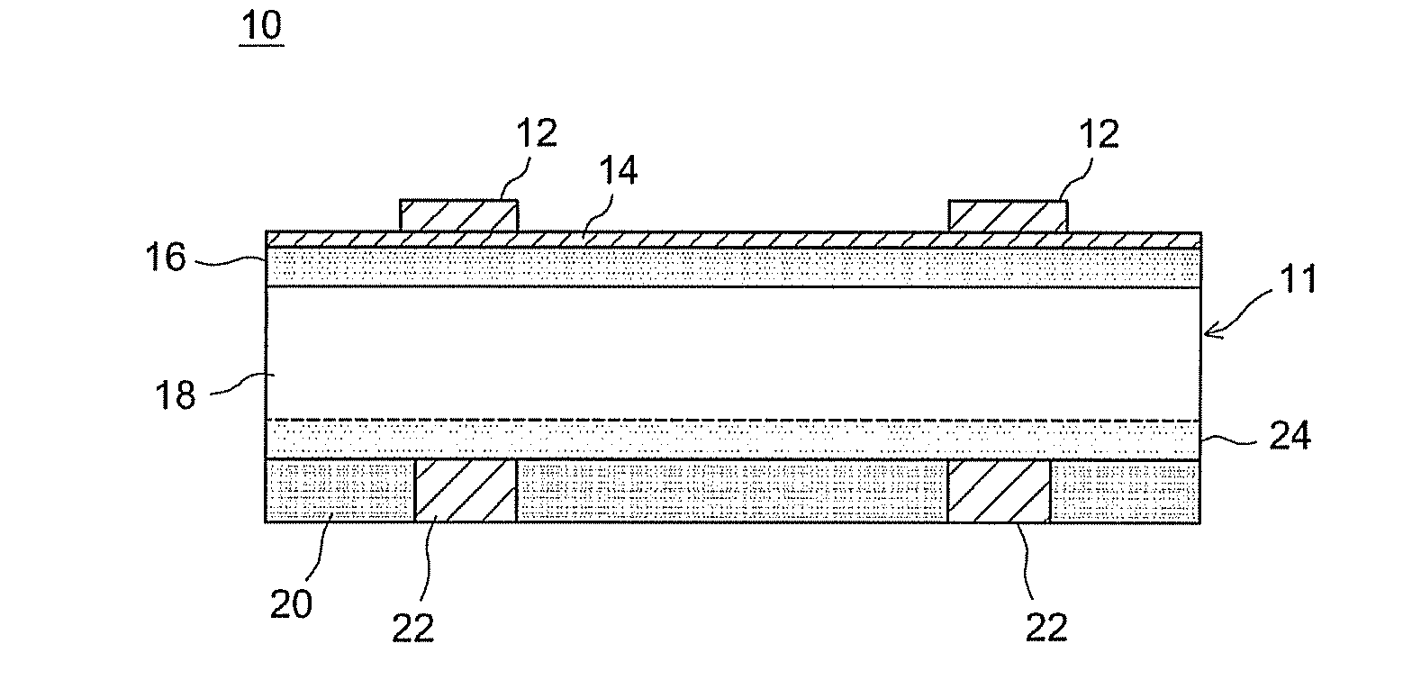
The paste composition for forming a back electrode of solar cell 10 provided by the present invention contains, as solids, an aluminum powder, a glass powder and a composite powder composed of a particulate composite of a metal oxide with a silicon-containing organic or inorganic compound. This composite powder is contained in an amount of at least 0.01 mass % but less than 0.45 mass % given 100 mass % as the total of the composite powder, the aluminum powder and the glass powder.

Description

BACKGROUND OF THE INVENTION[0001]1. Field of the Invention[0002]The present invention relates to a paste composition for a solar cell, and to a manufacturing method therefor. Specifically, it relates to an aluminum-containing paste composition for forming an aluminum electrode (as a back electrode) on the back side of the light-receiving surface of crystal silicon solar cell, and to a manufacturing method therefor.[0003]The priority claim for the present application is based on Japanese Patent Application No. 2009-297944 submitted on Dec. 28, 2009, and the entire contents of that application are incorporated by reference in this Description.[0004]2. Description of the Related Art[0005]A typical example of solar cell for converting the light energy of the sun into electricity is the so-called crystal silicon solar cell, a solar cell that uses crystalline (single-crystal or multi-crystal) silicon for the semiconductor substrate. An example of such a crystal silicon solar cell is the m...

Claims


Application Information

Patent Timeline
Patent Type & Authority Applications(United States)
IPC IPC(8): H01B1/02
CPCH01B1/16Y02E10/50H01L31/022425
Inventor OCHI, KOSUKESENDA, SHINJIYAMAGISHI, MASAOKUME, MAMIKO
Owner NORITAKE CO LTD
Learn More