Embossing assembly, manufacturing method thereof, and embossing method using the same

a technology of embossing assembly and manufacturing method, which is applied in the direction of dough shaping, manufacturing tools, instruments, etc., can solve the problems of limited manufacturing efficiency of the molding process, difficult to form the microstructure of the roller by machine cutting, and relatively high cos

Inactive Publication Date: 2011-06-30
HON HAI PRECISION IND CO LTD
View PDF2 Cites 6 Cited by
  • Summary
  • Abstract
  • Description
  • Claims
  • Application Information

AI Technical Summary

Problems solved by technology

However, the insert-molding process provides only limited manufacturing efficiency, and sprue material is unavoidably generated during the insert-molding process, indicating material waste.
However, since the roller is substantially cylindrical, when the light guide plate to be formed has a plurality of complex micro-structures, the corresponding micro-structures on the roller are difficult to be formed by machine cutting and relatively costly.

Method used


Image

  • Embossing assembly, manufacturing method thereof, and embossing method using the same
  • Embossing assembly, manufacturing method thereof, and embossing method using the same
  • Embossing assembly, manufacturing method thereof, and embossing method using the same

Examples


Embodiment Construction

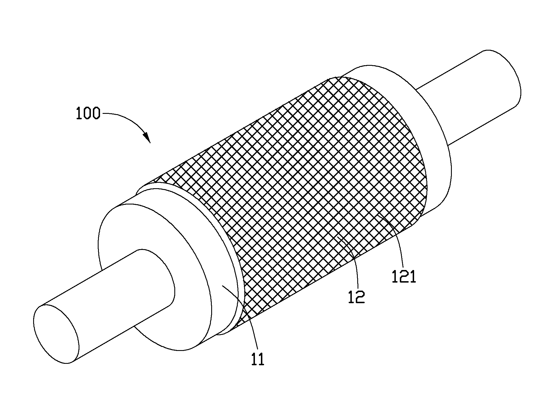
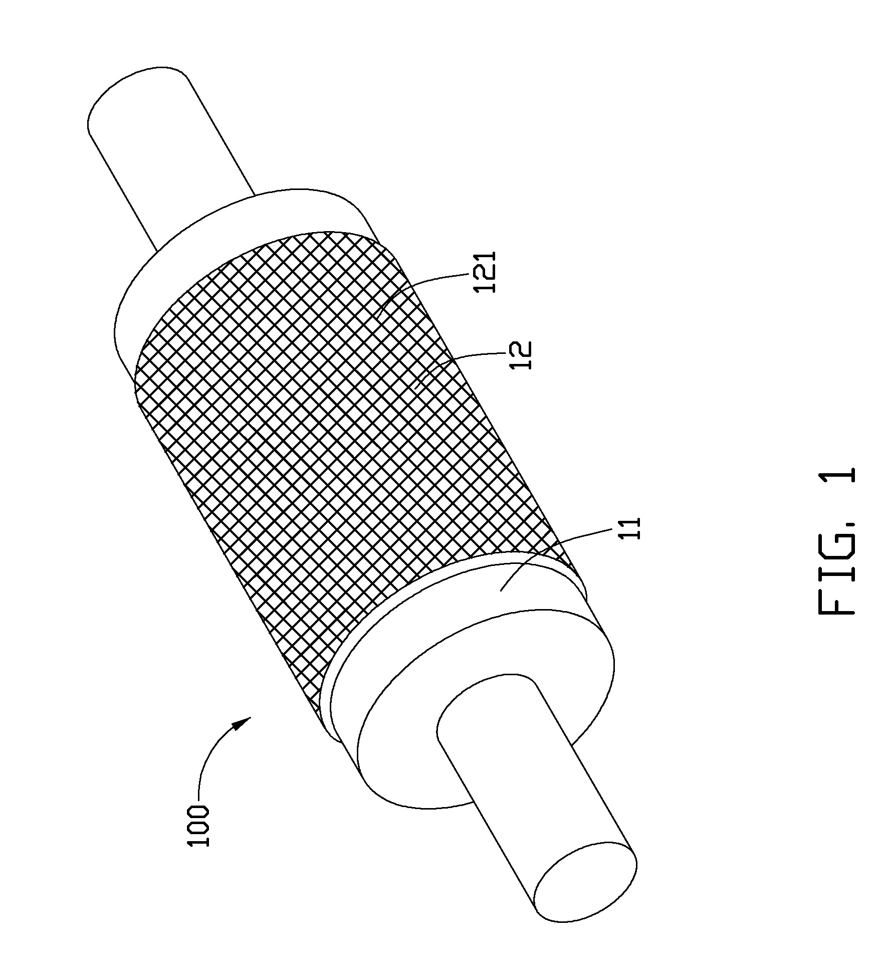
[0013]Referring to FIG. 1, one embodiment of an embossing assembly 100 includes a roller 11 and an embossing layer 12 applied on the roller 11. The embossing layer 12 can be formed by electroforming and includes a plurality of embossing micro-structures 121 formed on an outer surface of the embossing layer 12. The embossing micro-structures 121 are rigid and arranged in a matrix. The embossing micro-structures 121 may be substantially drop point-shaped, prism, protrusion or groove extending along a curve, or combination thereof. When the embossing layer 12 is rolled on a substrate, a plurality of micro-structures is formed on the substrate corresponding to the embossing micro-structures 121.

[0014]The roller 11 may be made of a thermally conductive material, such as aluminum, copper, zinc, nickel, iron, titanium, cobalt or an alloy thereof. The embossing layer 12 may be made of a thin flexible layer of electroforming material, such as nickel, platinum-nickel-cobalt, cobalt-tungsten, ...


PUM

PropertyMeasurementUnit
micro-structuresaaaaaaaaaa
micro-structureaaaaaaaaaa
optical propertiesaaaaaaaaaa

Abstract

A light guide plate is manufactured by applying an embossing assembly. The embossing assembly includes a roller and an embossing layer applied on the roller. The embossing assembly is formed by electroforming embossing micro-structures on the outer surface of the embossing layer to an embossing substrate and embossing micro-structures on a surface thereof.

Description

CROSS-REFERENCE TO RELATED APPLICATION[0001]This application is related to a co-pending U.S. patent application Ser. No. 12 / 758,128, filed on Apr. 128, 2010, and entitled “EMBOSSING ASSEMBLY, MANUFACTURING METHOD THEREOF, AND EMBOSSING METHOD USING THE SAME”. The inventors of the co-pending application are Hsi-Chang Wu and Tai-Cherng Yu. The co-pending application has the same assignee as the present application. The Specification and Drawings of the co-pending application are incorporated herein by reference.BACKGROUND[0002]1. Technical Field[0003]The present disclosure generally relates to an embossing assembly, a method of manufacturing the embossing assembly, and a method of embossing light guide plates using the embossing assembly.[0004]2. Description of Related Art[0005]Backlight modules are critical components of a liquid crystal display, such as those used in a mobile phone or digital camera. A commonly used backlight module generally includes a light guide plate to optimize...

Claims


Application Information

Patent Timeline
Patent Type & Authority Applications(United States)
IPC IPC(8): G02B1/12B28B11/08C25D5/48
CPCB29C59/04B29C2059/023B29D11/00288B29D11/00663G02B6/0065C25D5/48G02B5/0268G02B6/0035C25D1/04
Inventor LIN, DA-WEIWU, HSI-CHANG
Owner HON HAI PRECISION IND CO LTD
Why Eureka
Try Eureka