Test apparatus and test method
a test apparatus and test method technology, applied in the direction of measuring devices, automatic control, instruments, etc., can solve the problem of relatively large q side of the iq modulator, and achieve the effect of increasing time margin and small loop latency
- Summary
- Abstract
- Description
- Claims
- Application Information
AI Technical Summary
Benefits of technology
Problems solved by technology
Method used
Image
Examples
Embodiment Construction
Hereinafter, an embodiment of the present invention will be described. The embodiment does not limit the invention according to the claims, and all the combinations of the features described in the embodiment are not necessarily essential to means provided by aspects of the invention.
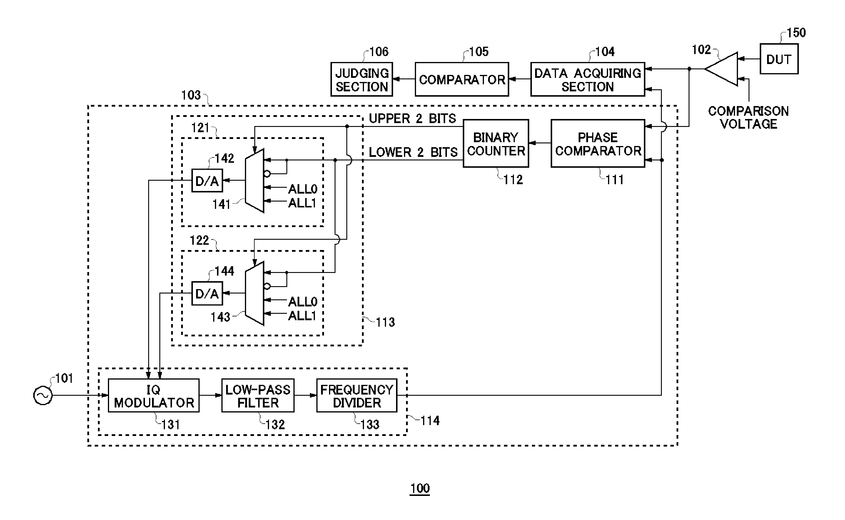
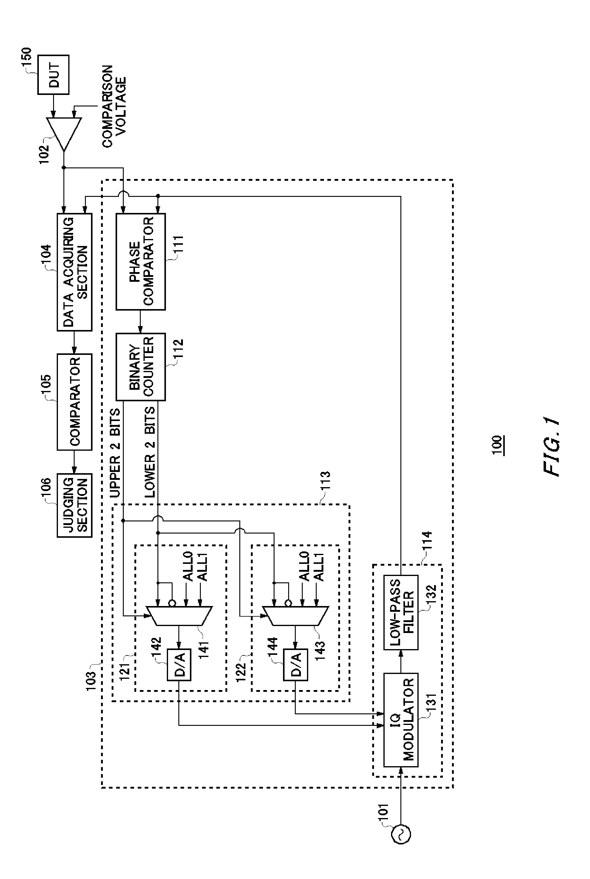
FIG. 1 illustrates a configuration example of a test apparatus 100 according to an embodiment. The test apparatus 100 includes a reference clock source 101, a level comparator 102, a recovered clock generating circuit 103, a data acquiring section 104, a comparator 105 and a judging section 106.
The reference clock source 101 generates an alternating current signal. The alternating current signal generated by the reference clock source 101 is referred to as a reference clock. A frequency of the reference clock is referred to as a reference frequency. The reference clock source 101 outputs the generated reference clock to a hereunder described IQ modulator 131 in the recovered clock generating circuit 103...
PUM
 Abstract
Description
Claims
Application Information
 - R&D
- Intellectual Property
- Life Sciences
- Materials
- Tech Scout
- Unparalleled Data Quality
- Higher Quality Content
- 60% Fewer Hallucinations
Browse by: Latest US Patents, China's latest patents, Technical Efficacy Thesaurus, Application Domain, Technology Topic, Popular Technical Reports.
© 2025 PatSnap. All rights reserved.Legal|Privacy policy|Modern Slavery Act Transparency Statement|Sitemap|About US| Contact US: help@patsnap.com


