Uses of Electromagnetic Interference Patterns

a technology of electromagnetic interference and pattern, applied in the field of spatial metrology, can solve the problems of complex system, low accuracy of encoder, and inability to achieve the preciseness of the system, and achieve the effect of simple thermal management at the object location

Active Publication Date: 2011-06-30
THE UNIV COURT OF THE UNIV OF GLASGOW
View PDF28 Cites 50 Cited by
  • Summary
  • Abstract
  • Description
  • Claims
  • Application Information

AI Technical Summary

Benefits of technology

[0138]In another permutation, the coherent light source and the optical element and the detector may be fixed with respect to each other. In this case the object may include reflecting means to reflect at least a portion of the intensity pattern to the detector, so that movement of the object can be detected. This has the advantage that the object need not have an active, power-consuming device at its location, and therefore thermal management at the object location is more straightforward.
[0139]In another permutation, the coherent light source and the optical element may not be fixed with respect to each other. In this case, the coherent light may be transmitted to the optical element along an optical path such as an optical fibre, for example. In this case, the optical element may be fixed with respect to the object. The detector may be fixed with respect to the coherent light source. Again, in this case, there is the advantage that the object need not have an active, power-consuming device at its location.
[0140]The present inventors further consider that the system may be operated using two or more wavelengths of electromagnetic radiation (typically light). The advantage of this is that there may then be provided a corresponding number of intensity patterns. These may be generated by the same generator. However, it is preferred that each wavelength is guided, typically within a single optical element, towards corresponding apertures in the optical element in order to generate the intensity patterns. The intensity patterns of differing wavelengths may be detected, at least in part, on the basis of wavelength (e.g. via filtering). Additionally or alternatively, the intensity patterns of differing wavelengths may be detected, at least in part, on the basis of spacing of maxima and / or minima in the pattern. Conveniently, as the light source, there may be used a laser which is capable of outputting two wavelengths, e.g. a DPY laser. Preferably, the intensity patterns of different wavelengths have different rotational periodicity.

Problems solved by technology

These systems are (usually) inexpensive, quite precise and very inaccurate.
Such “encoders” are complex systems and are very accurate, but have a precision not much better than a simple LVDT.
A particular problem with such systems is that the accuracy of the system is defined by the grating.
These rulers are expensive, massive and often require careful environmental control to prevent them from becoming contaminated.
The production of a 2-dimensional grating (for example to measure x-y or rotation) is very expensive and not generally possible for very large scales.
Interferometers have a number of problems, however.
Firstly the signal produced by a monochromatic interferometer is intrinsically periodic, so that the identification of a particular position (“zero” distance) is difficult.
The angular accuracy of this arrangement is subject to errors in physical construction.
This requires the use of very expensive mirrors.

Method used


Image

  • Uses of Electromagnetic Interference Patterns
  • Uses of Electromagnetic Interference Patterns
  • Uses of Electromagnetic Interference Patterns

Examples


Embodiment Construction

[0179]The measurement of position is a very important task in modern technology. The preferred embodiments of the present invention permit position to be measured with extremely high precision at very low cost. The preferred embodiments provide physically small and highly configurable systems.

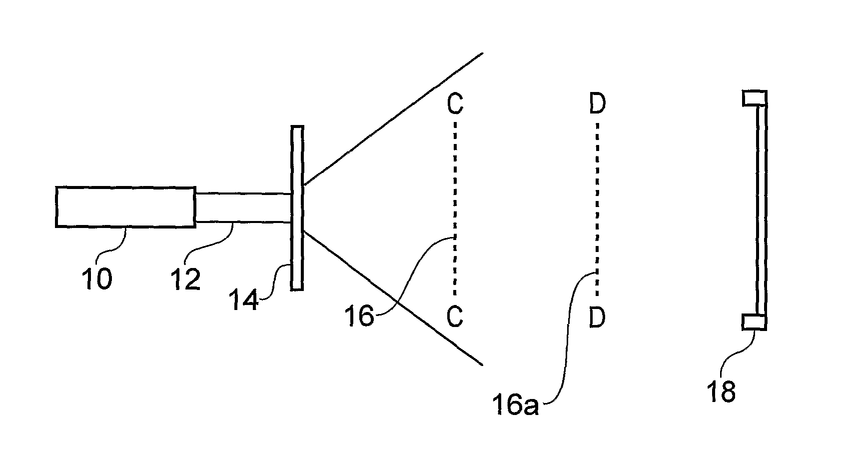
[0180]We first set out here in simple terms the way in which the system works, based on a notional example of an optical system consisting of a photographic projector and a screen. An image is projected onto the screen. Typically, the picture is slightly smaller than the screen. In a first case, the projector is head-on to the screen, so the image is “square” to the screen. In a second case, if the projector is moved closer to the screen, then the image gets smaller. Thus the size of the image on the screen is a measure of how far away the projector is from the screen. If the size of the image on the screen is measured, this allows the distance from the projector to the screen to be determined....


PUM


Abstract

Various uses of visible light interference patterns are provided. Suitable interference patterns are those formed by diffraction from patterns of apertures. Typical uses disclosed herein relate to spatial metrology, such as a translational and/or angular position determination system. Further uses include the analysis of properties of the light itself (such as the determination of the wavelength of the electromagnetic radiation). Still further uses include the analysis of one or more properties (e.g. refractive index) of the matter through which the light passes. Part of the interference pattern is captured at a pixellated detector, such as a CCD chip, and the captured pattern compared with a calculated pattern. Very precise measurements of the spacing between maxima is possible, thus allowing very precise measurements of position of the detector in the interference pattern.

Description

BACKGROUND TO THE INVENTION[0001]1. Field of the Invention[0002]The present invention provides various uses of electromagnetic interference patterns, and particularly (but not exclusively) to uses of visible light interference patterns, UV interference patterns and IR interference patterns. Typical uses disclosed herein relate to spatial metrology, such as a translational and / or angular position determination system, and to methods for such position determination. Further uses include the analysis of properties of the electromagnetic radiation itself (such as the determination of the wavelength of the electromagnetic radiation). Still further uses include the analysis of one or more properties (e.g. refractive index) of the matter through which the electromagnetic radiation passes.[0003]2. Related Art[0004]U.S. Pat. No. 4,111,557 discloses a method for determining the shape or position of an object with respect to the shape or position of a reference object. The reference object may...

Claims


Application Information

Patent Timeline
Patent Type & Authority Applications(United States)
IPC IPC(8): G01B11/02
CPCG01D5/266G01D5/38G01D11/00G03H1/0005G01J2009/0234G01N21/45G01J9/0246G01B11/2441G01J9/02G01S17/06
Inventor WEAVER, JONATHAN MARK RALPHDOBSON, PHILLIP STEPHENBURT, DAVID PAULTHOMS, STEPHENDOCHERTY, KEVIN EDWARDZHANG, YUAN
Owner THE UNIV COURT OF THE UNIV OF GLASGOW
Why Eureka
Try Eureka