Radiographic apparatus

Inactive Publication Date: 2011-06-30
SHIMADZU CORP
View PDF2 Cites 8 Cited by
  • Summary
  • Abstract
  • Description
  • Claims
  • Application Information

AI Technical Summary

Benefits of technology

According to the radiographic apparatus of this invention, the scattered radiation removing device is constructed such that the absorbing layers, which absorb scattered radiation, are arranged in a direction parallel to at least one of the directions of rows and columns of detecting elements, and that the spacing between adjacent shadows among the shadows of the absorbing layers formed on the radiation detecting device as a result of the absorbing layers absorbing radiation is larger than the spacing between the pixels forming the radiological image. With this construction, pixels without shadows (shadowless pixels) appear in every row or column of detecting elements parallel to the direction of arrangement of the absorbing layers. Therefore, the grid data acquiring device acquires grid data in the absence of a subject and in the presence of the scattered radiation removing device, and the shadowless pixel calculating device determines pixels without shadows based on the shadows in the grid data acquired by the grid data acquiring device. At this time, the pixels without shadows which actually appear, and the pixels without shadows determined are substantially in agreement. The shadow total quantity calculating device calculates a total quantity of shadows per absorbing layer, based on the pixels without shadows provided by the above shadowless pixel calculating device. That is, the quantity of blocked radiation in enclosed areas including the shadowless pixels can be regarded as the total quantity of shadows per absorbing layer.
On the other hand, the first image data acquiring device acquires image data in the presence of the subject and scattered radiation removing device. The image data smoothing device smoothes the image data acquired by the first image data acquiring device along the direction of extension of the absorbing layers. Consequently, the influence of the subject is canceled from the image data smoothed by the image data smoothing device, and only the profile of shadows having a substantially constant value remains therein. Therefore, the image data smoothed by the image data smoothing device includes only the profile of shadows, with the influence of the subject canceled, while retaining the data of the subject.
Even when a shadow straddles a plurality of pixels or the shadow position moves relative to the pixels, the total quantity of shadows per absorbing layer can be regarded as constant. So, from the total quantity of shadows per absorbing layer provided by the shadow total quantity calculating device, and based on the total quantity of shadows, the image data correcting device corrects the image data smoothed by the image data smoothing device. This correction can cancel the disturbance by the subject, to provide a profile of shadows at an actual time of radiological image pickup of the subject. Therefore, even when a shadow straddles a plurality of pixels or the shadow position moves relative to the pixels, the second image data acquiring device can determine data after shadow removal, based on the image data corrected by the above image data correcting device and the image data acquired by the above first image data acquiring device, and acquire the data after shadow removal as final image data. As a result, the shadow removal can be carried out with high accuracy by using the corrected image data which is the profile of shadows at an actual time of radiological image pickup of the patient.
In one example of the invention described above, the radiographic apparatus further comprises a pixel classifying device for classifying pixels in the

Problems solved by technology

However, this air grid has a larger internal structure than the usual grid, which makes it difficult to remove the shadows by the above-noted spatial frequency processing.
However, such X-ray transmittances cannot be applied directly to actual image pick-up data by using equation (2) above.
It is not realistic f

Method used


Image

  • Radiographic apparatus
  • Radiographic apparatus
  • Radiographic apparatus

Examples


Example

A preferred embodiment of this invention will be described in detail hereinafter with reference to the drawings.

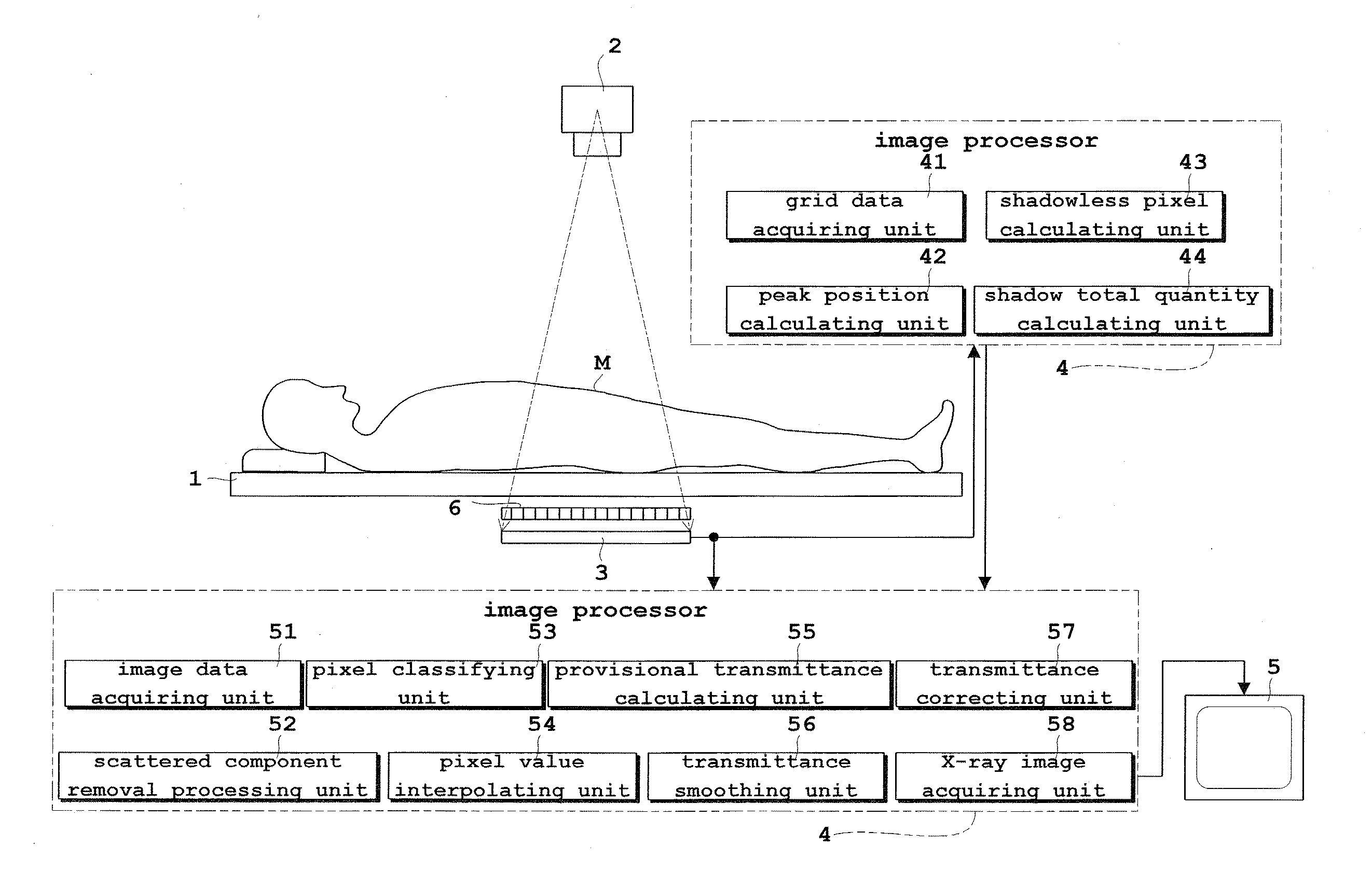
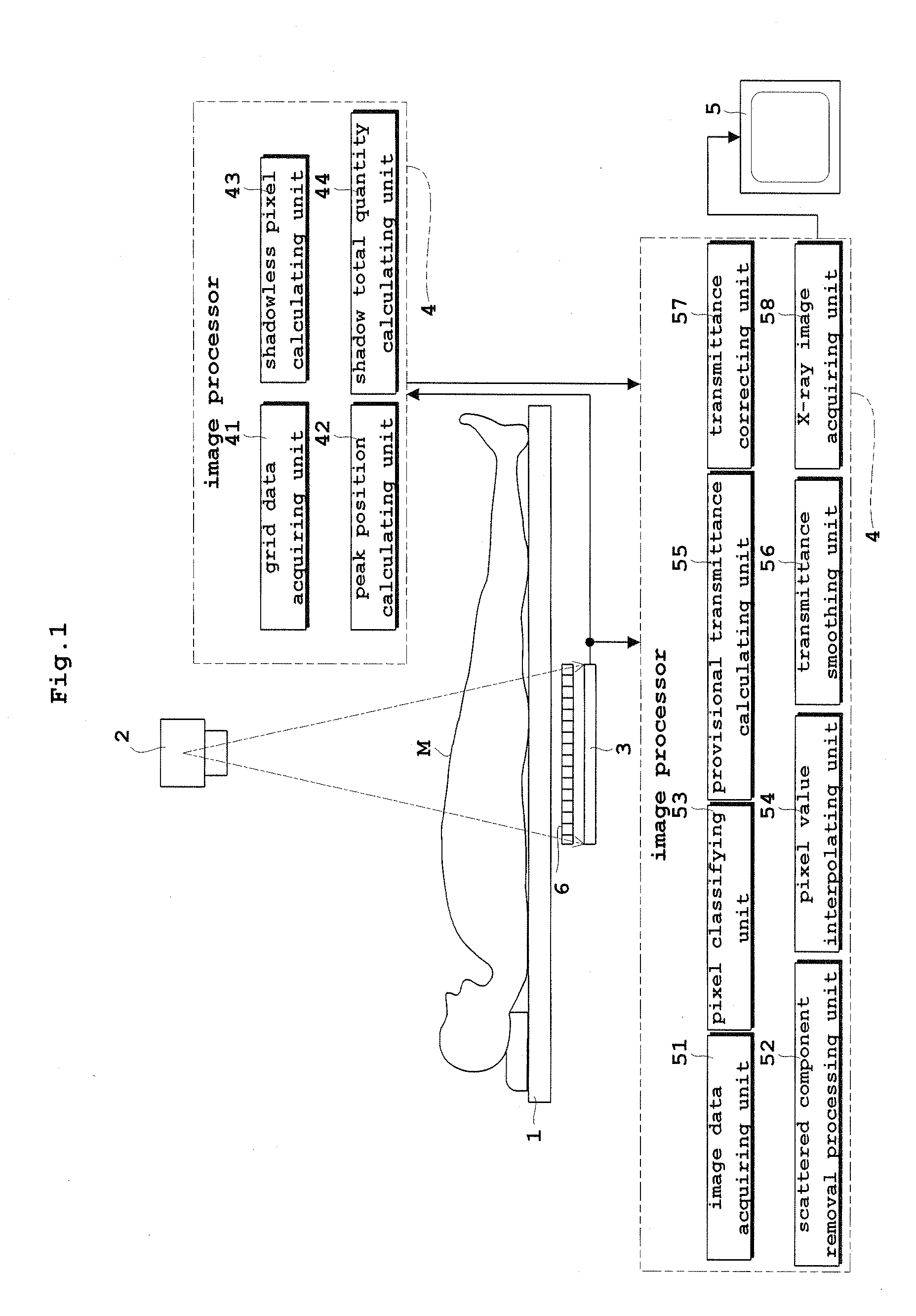
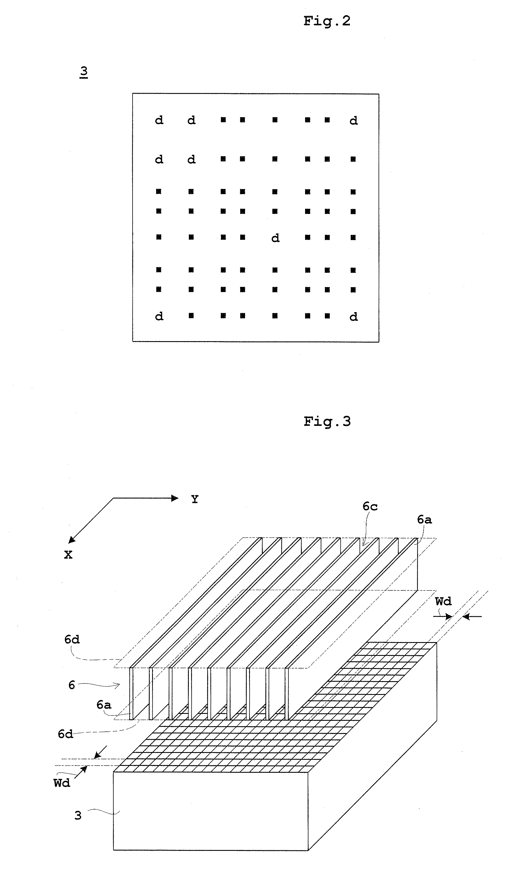
FIG. 1 is a block diagram of an X-ray imaging apparatus according to this invention. FIG. 2 is a schematic view of a detecting plane of a flat panel X-ray detector (FPD). FIG. 3 is a schematic view of an air X-ray grid according to this invention. FIG. 4A is a perspective view showing an outline of the air grid and FPD together with an X-ray tube. FIG. 4B is an enlarged view of peripheries of the air grid. FIG. 4C is a sectional view seen from arrow A of FIG. 4B. This embodiment will be described taking X-rays as an example of radiation.

As shown in FIG. 1, the X-ray imaging apparatus according to this invention includes a top board 1 for supporting a subject M, an X-ray tube 2 for emitting X-rays toward the subject M, a flat panel X-ray detector (hereinafter abbreviated as “FPD”) 3 for detecting the X-rays emitted from the X-ray tube 2 and transmitted through the subject M...


PUM


Abstract

An air grid is constructed such that absorbing foil strips, which absorb scattered X-rays, are arranged in a direction parallel to the direction of rows of detecting elements, and that spacing between adjacent shadows among shadows of the absorbing foil strips formed on a flat panel X-ray detector (FPD) as a result of the absorbing foil strips absorbing X-rays is larger than spacing between pixels forming an X-ray image. An image data acquiring unit, a transmittance smoothing unit, a grid data acquiring unit, a shadowless pixel calculating unit, a shadow total quantity calculating unit, a transmittance correcting unit and an X-ray image acquiring unit are provided to remove the shadows with high accuracy by using corrected image data (X-ray transmittances) which constitutes a profile of shadows occurring at an actual time of X-ray imaging of a subject.

Description

BACKGROUND OF THE INVENTION(1) Field of the InventionThis invention relates to a radiographic apparatus using a flat panel radiation detector, and more particularly to a technique for removing scattered radiation.(2) Description of the Related ArtDescription will be made taking X-rays as an example of radiation. In many X-ray imaging apparatus, a scattered X-ray removing grid (scattered radiation removing device) is used to prevent a lowering of image quality due to scattered X-rays (hereinafter referred to simply as “scattered rays”) generated when X-rays are transmitted through a subject to be imaged. An ordinary grid is formed of an alternate arrangement of absorbing foil strips which absorb the scattered rays and intermediate layers which transmit the X-rays. However, when such a grid is used, the structure of the grid (absorbing foil strips) will be projected to as shadows. It is therefore necessary to remove the shadows of the grid.A commonly used grid has a fine structure, an...

Claims


Application Information

Patent Timeline
IPC IPC(8): G01N23/04
CPCA61B6/00A61B6/4028A61B6/4291G06T2207/10116G06T5/005A61B6/5252
Inventor HIROOKA, KEN
Owner SHIMADZU CORP
Why Eureka
Try Eureka