
Systems and methods for purging UV curing tubes

a technology of purging system and curing tube, which is applied in the direction of drying machine with progressive movement, lighting and heating apparatus, furnace, etc., can solve the problems of volatile deposits on the inner surface of the center tube, inability to complete curing, and portion of the uncured coating material to volatilize (or off-gas), so as to reduce the surface contamination of the cure tube

Active Publication Date: 2011-06-30
OFS FITEL LLC
View PDF5 Cites 3 Cited by
  • Summary
  • Abstract
  • Description
  • Claims
  • Application Information

AI Technical Summary

Benefits of technology

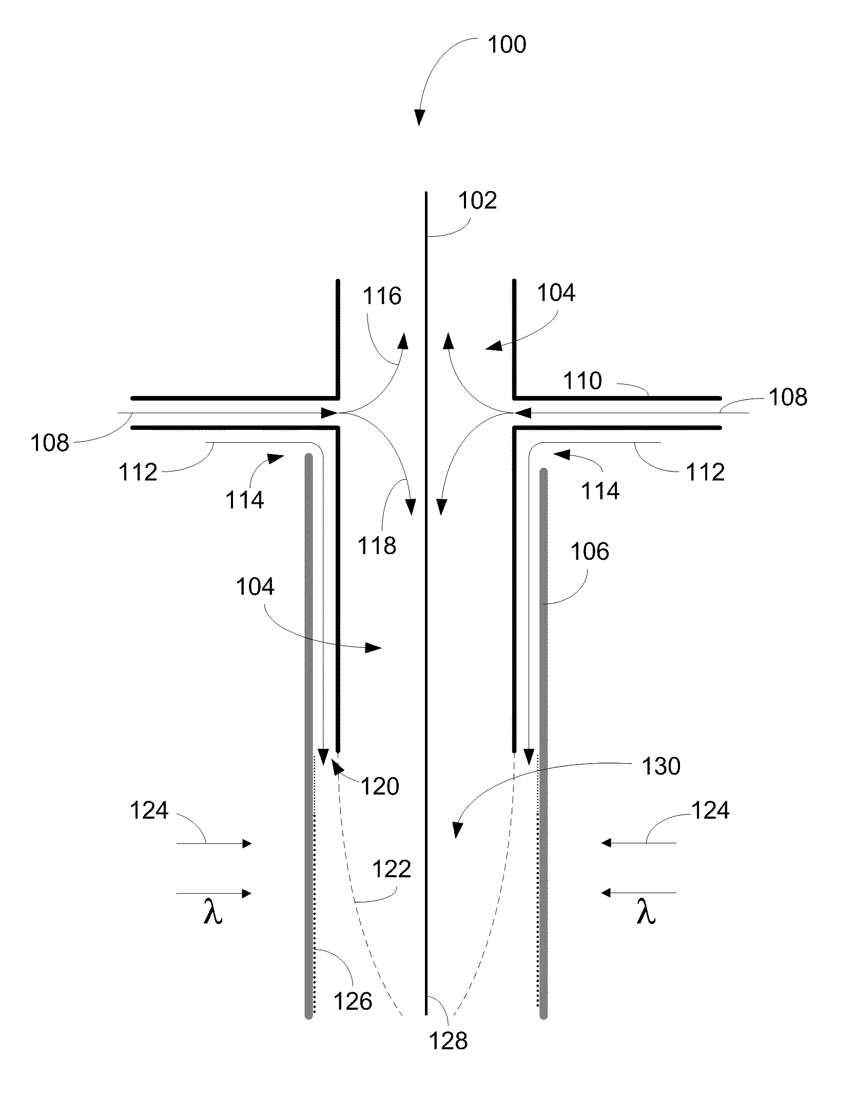
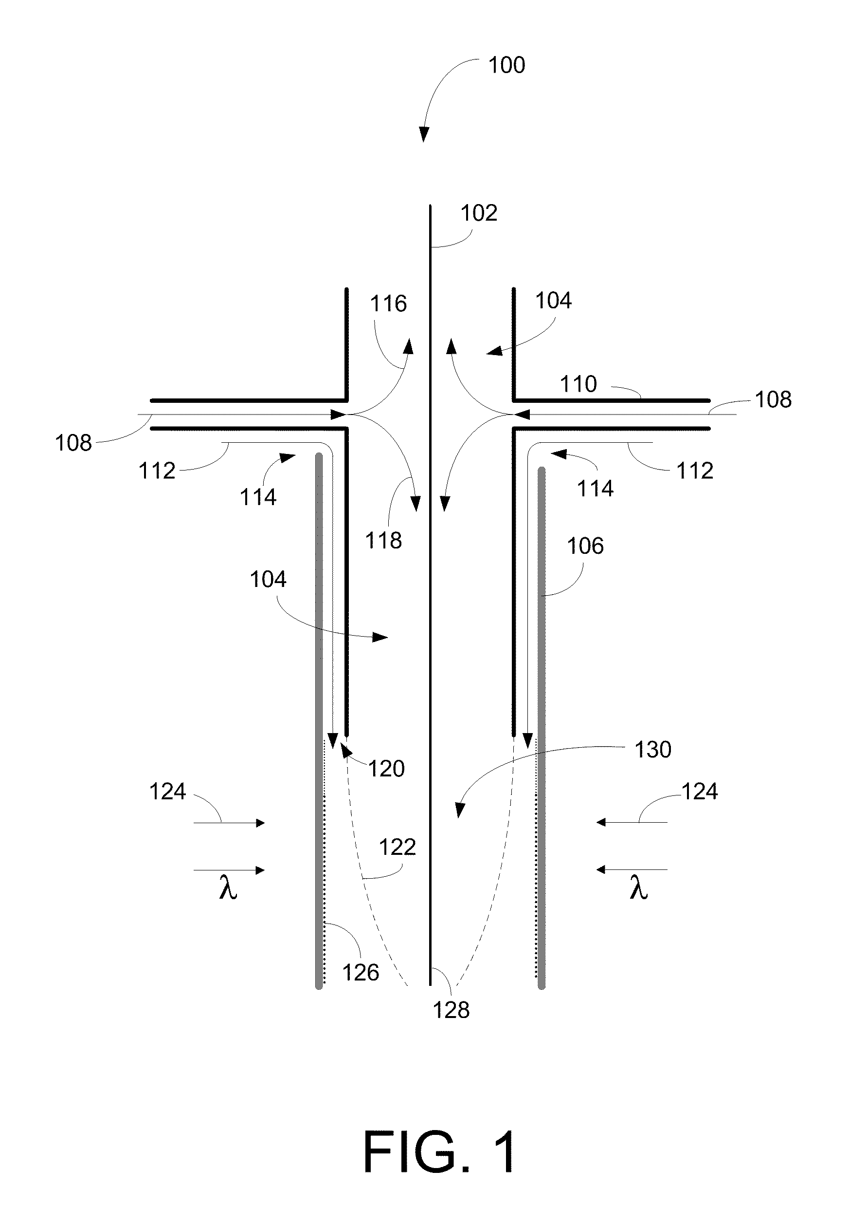
According to another example embodiment, a system is provided for reducing cure tube surface contamination while curing a coated optical fiber. The system includes a curing oven comprising a radiation source, a gas chamber operable for surrounding the coated optical fiber with a predetermined gas, a cure tube coupled to the gas chamber and configured to transmit radiation from the radiation source to the coated optical fiber, and a purge gas inlet for releasing purge gas into the cure tube to purge at least a portion of the inner surface of the cure tube with a purge gas.
According to another example embodiment, an apparatus is provided for reducing cure tube surface contamination while curing a coated optical fiber. The apparatus includes a gas chamber operable for surrounding the coated optical fiber with a predetermined gas, a cure tube coupled to the gas chamber and operable to transmit radiation from the radiation source to the coated optical fiber, and a purge gas inlet for releasing purge gas into the cure tube to purge at least a portion of the inner surface of the cure tube with a purge gas.

Problems solved by technology

However, it is known that atmospheric oxygen can react with certain coating materials to form peroxy radicals that can interfere with the curing process and may cause incomplete curing, particularly at the surface of the coating where the oxygen is present.
The elevated temperature can cause a portion of the uncured coating material to volatize (or off-gas) and, unfortunately, the volatiles can form deposits on the inner surface of the center tube.
These coating deposits can cause significant clouding on the inner surface of the center tube and can severely attenuate the UV curing light to the point where the fiber coatings may not be sufficiently cured.

Method used


Image

  • Systems and methods for purging UV curing tubes
  • Systems and methods for purging UV curing tubes
  • Systems and methods for purging UV curing tubes

Examples


Embodiment Construction

Embodiments of the invention will be described more fully hereinafter with reference to the accompanying drawings, in which embodiments of the invention are shown. This invention may, however, be embodied in many different forms and should not be construed as limited to the embodiments set forth herein; rather, these embodiments are provided so that this disclosure will be thorough and complete, and will fully convey the scope of the invention to those skilled in the art. Like numbers refer to like elements throughout.

Certain embodiments of the invention may enable purging of UV cure tubes (also known as center tubes) while curing optical fiber coatings. According to certain example embodiments, a purge gas comprising oxygen may be used to selectively purge at least a portion of the inner surface of a cure tube in order to reduce the build-up of deposits on the cure tube while maintaining an inert environment around the optical fiber during cure. Accordingly, the reduction or remova...


PUM

PropertyMeasurementUnit
Fractionaaaaaaaaaa
Fractionaaaaaaaaaa
Fractionaaaaaaaaaa

Abstract

Certain embodiments of the invention may include systems and methods curing a coated optical fiber. The method includes drawing the coated optical fiber through a gas chamber filled with a predetermined gas, drawing the fiber through a cure tube coupled to the gas chamber, and purging at least a portion of an inner surface of the cure tube with a purge gas as the coated optical fiber is drawn through the cure tube.

Description

FIELD OF THE INVENTIONThis invention generally relates to ultraviolet (UV) curing, and more particularly, to purging UV curing tubes.BACKGROUND OF THE INVENTIONRadiation curable materials are used extensively in the production of optical fiber, particularly in the production of protective coatings that surround the optical fiber. One class of radiation curable materials can be converted from a liquid to a solid upon exposure to light energy in the ultraviolet (UV) spectrum, e.g., wavelengths ranging from about 200 to about 400 nanometers. Most UV radiation curable materials contain a monomer and oligomer mixture with an added photo-initiator package that facilitates cross-linking upon exposure to the radiation. The extent of the cross-linking reaction is dependent upon the amount of exposure to the radiation.The coatings surrounding an optical fiber can be quickly cured by drawing the coated optical fiber past a high power UV curing lamp at a speed proportional to the radiation dens...

Claims


Application Information

Patent Timeline
IPC IPC(8): B05B13/00B05D5/06
CPCB05D3/0466B05D3/066B05D3/067B05D2203/35F26B21/14C03C25/6226F26B3/283F26B13/002B05D2256/00
Inventor HASLOV, PETERKONSTADINIDIS, KARIOFILISGARNER, HARRY
Owner OFS FITEL LLC
Learn More