
Ceramic Particles With Controlled Pore and/or Microsphere Placement and/or Size and Method Of Making Same

a ceramic particle and microsphere technology, applied in the direction of sealing/packing, earthwork drilling and mining, wellbore/well accessories, etc., can solve the problems of reducing the overall strength of the ceramic particle, reducing the strength of the resulting pore containing ceramic particle, and conventional proppants offered for sale exhibit exceptional crush strength but also extreme density, so as to achieve the effect of superior balance of crush strength and/or buoyancy

Inactive Publication Date: 2011-06-30
HALLIBURTON ENERGY SERVICES INC
View PDF44 Cites 250 Cited by
  • Summary
  • Abstract
  • Description
  • Claims
  • Application Information

AI Technical Summary

Benefits of technology

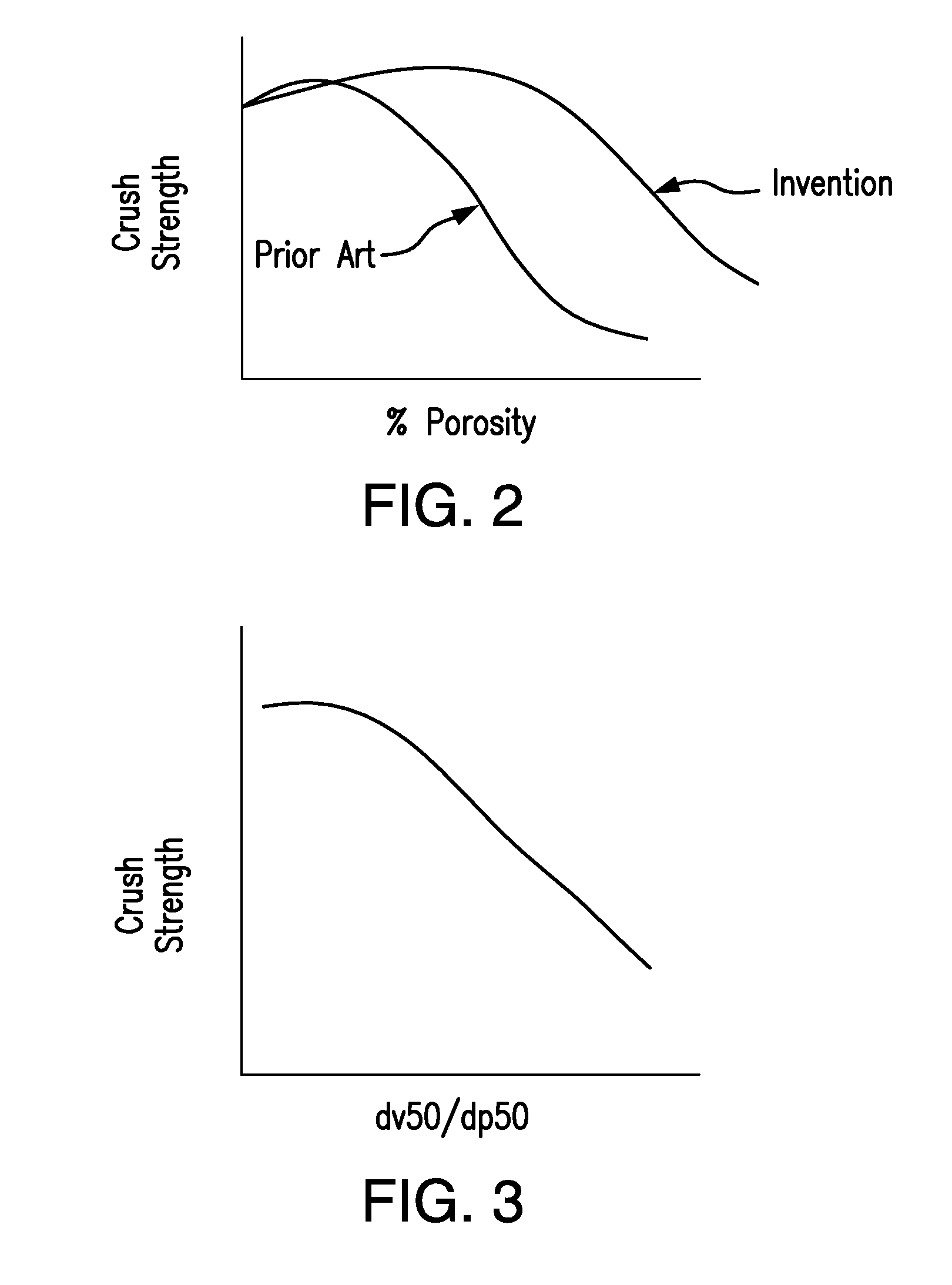
[0040]FIG. 2 is a crush strength vs microsphere (or pore) placement and / or size diagram showing the relationship between these two variables and showing an advantage of the present invention.
[0041]FIG. 3 is a diagram showing the relationship between the ratio of microsphere (or pore) size to particle size (dv50 / dp50) to crush strength and its significance in the present invention.
[0042]FIG. 4 is a diagram showing the radial distribution of microspheres (or pores) in a ceramic particle including a hollow template.
[0043]FIG. 5 is a diagram showing the radial distribution of microspheres (or pores) in a ceramic particle comprising a hollow template and multiple layers of ceramic material.
[0044]FIG. 6 is a diagram showing a continuously varying distribution of microspheres (or pores) in a ceramic particle that does not include a template.
[0045]FIG. 7 is a diagram showing the uniform radial distribution of microspheres (or pores) in a ceramic particle that does not include a template.

Problems solved by technology

The introduction of pores into a ceramic body, however, typically causes a decrease in strength of the resulting pore containing ceramic particle.
The pores function as flaws in the surface structure that decreases the overall strength of the ceramic particle.
Conventional proppants offered for sale exhibit exceptional crush strength but also extreme density.
Sand is low cost and light weight, but low strength; man-made ceramics, mainly bauxite-based ceramics or mullite based ceramics are much stronger than sand, but heavier.
Second, resin-coated sands are “tacky” and thus exhibit reduced “proppant flow-back” relative to conventional sand proppants (e.g. the proppant stays in the formation better).
Third, resin coating typically increases sphericity and roundness thereby reducing flow resistance through the proppant pack.
The production of silicon dioxide and either carbon monoxide or carbon dioxide weakens the resulting proppant.
Although, the liquid phase sintering approach assists with the densification, the properties of such a system are less than optimal and fail to reach the intrinsic properties that these materials are capable of, due primarily to the effects of a relatively weak phase existing at the grain boundaries of the ceramic material.
In addition, with the liquid phase sintering approach, a high level of shrinkage occurs during sintering.

Method used


Image

  • Ceramic Particles With Controlled Pore and/or Microsphere Placement and/or Size and Method Of Making Same
  • Ceramic Particles With Controlled Pore and/or Microsphere Placement and/or Size and Method Of Making Same
  • Ceramic Particles With Controlled Pore and/or Microsphere Placement and/or Size and Method Of Making Same

Examples


example 1

[0515]SiC-cordierite composites were made using ceramic processing. SiC powder (Grade 0.7 μm, Electro Abrasives Corporation, 701 Willet Road, Buffalo, N.Y. 14218) with an average particle size of 0.7 μm and a surface area (BET) of 10 m2 / g, and cordierite powder (KC-300, TradeGroup Asia Limited, Unit 2703 Golden Centre, 188 Des Voeux Road-Central, Hong Kong) with a particle size of 44 μm (−325 mesh), were employed. A series of test samples were prepared with different percentages of SiC powders homogenously mixed with the cordierite. The cordierite powder was attrition-milled to an average particle size of around 2 μm, and then mixed with the SiC powders in deionized (DI)-water, and ball-milled in a plastic jar with high purity alumina media, for 4 hours. The slurry was dried in an oven at 125° C. for 4-8 hours and the dry powder was sieved through a −80 mesh screen. Pellets Φ0.5″×0.2″ uniaxially were pressed at 12 MPa and sintered at 1230° C.-1270° C. from 4 h to 6 h in air. After t...

example 2

[0521]Using the same process as in Example #1, 10% wt of SiC powder was mixed with the balance of mullite powder, MULCOA 47® (C-E Minerals, King of Prussia, Pa.). The pellets were sintered at 1450° C. for 2 hours in air. The Table below shows the specific gravity, microsphere total volume and crush strength measured.

MicrosphereplacementMaterialsSGand / or sizeStrength psi10% SIC25-Mullite2.4714.3%9570

example 3

[0522]In this example, the effects of using pore formers in proppants were studied. In particular, a pore former, silicon carbide, was used in forming proppants. As a comparison, some proppants were prepared without pore formers. Specifically, proppants were prepared based on the components listed for each sample. In each case, the materials used to form the proppants were in powder form co-milled together in an attrition mill as a wet slurry (using water), and sprayed onto cenosphere templates (TG 425 grade template) to form green bodies. The sintering conditions (fired temperature) and time of sintering are provided for each sample. Prior to milling, each starting material had a size of 80 mesh or less. For the green bodies for each sample, a general mesh size of 300 to 500 microns was targeted with a median size of 430 to 450 microns for the green body. As can be seen by the results below, the use of a pore former, had a significant effect in reducing specific gravity, with only ...


PUM

PropertyMeasurementUnit
Temperatureaaaaaaaaaa
Fractionaaaaaaaaaa

Abstract

The present invention relates to lightweight high strength microsphere containing ceramic particles having controlled microsphere placement and / or size and microsphere morphology, which produces an improved balance of specific gravity and crush strength such that they can be used in applications such as proppants to prop open subterranean formation fractions. Proppant formulations are further disclosed which use one or more microsphere containing ceramic particles of the present invention. Methods to prop open subterranean formation fractions are further disclosed. In addition, other uses for the microsphere containing ceramic particles of the present invention are further disclosed, as well as methods of making the microsphere containing ceramic particles.

Description

[0001]This application claims the benefit under 35 U.S.C. §119(e) of prior U.S. Provisional Patent Application No. 61 / 291,649, filed Dec. 31, 2009, and prior U.S. Provisional Patent Application No. 61 / 308,131, filed Feb. 25, 2010, which are incorporated in their entirety by reference herein.BACKGROUND OF THE INVENTION[0002]The present invention relates to microsphere and / or pore containing ceramic particles used as proppants and for other uses. The present invention further relates to methods to make microsphere and / or pore containing ceramic particles to be used as proppants, reinforcing fillers, and other applications, such as where a combination of light weight and strength are required.[0003]For many ceramic articles including ceramic particles, it is desirable to increase the strength of the ceramic body while decreasing its specific gravity (density). A method commonly used to decrease the specific gravity of a ceramic particle is to introduce porosity into the body of the cer...

Claims


Application Information

Patent Timeline
IPC IPC(8): C09K8/80C04B35/78
CPCC04B35/195E21B43/267C04B35/62695C04B35/645C04B38/08C04B38/10C04B2235/3206C04B2235/3225C04B2235/3229C04B2235/3826C04B2235/528C04B2235/5409C04B2235/5427C04B2235/5436C04B2235/5445C04B2235/5463C04B2235/6581C04B2235/6584C04B2235/6585C04B2235/96C09K8/805C04B35/62204E21B43/26C04B35/565C04B35/71C04B38/00C04B38/0054C04B38/009C04B2235/3481C04B2235/5228C04B35/185C04B35/62605C04B35/64C04B38/0635C04B2235/3463C04B2235/48C04B2235/483C09K8/80E21B43/04
Inventor WU, SHANGHUAXIE, YUMINGCOKER, CHRISTOPHER E.CHATTERJEE, DILIP
Owner HALLIBURTON ENERGY SERVICES INC
Learn More