Gas cleaning method and apparatus

Inactive Publication Date: 2011-07-07
RE 2
View PDF1 Cites 15 Cited by
  • Summary
  • Abstract
  • Description
  • Claims
  • Application Information

AI Technical Summary

Benefits of technology

[0011]It is therefore an object of the present invention to provide a plasma method for purifying an offgas that contains organic and / or such inolganic pollutants as particulate matter, ash, heavy, which allows stable and safe operation.
[0012]It is another object of the present invention to provide such a method for purifying an offgas which require simple and short start-up procedures and is more flexible and safe with respect to sudden / frequent offgas feed rate changes with respect to prior art equipment.

Problems solved by technology

Another drawback of is the long transient that is needed to attain a full regime operation of conventional incineration equipment, and the low flexibility in case of variable feed throughput and / or quality, which in turn may be a cause of partial oxidation and toxic exhaust release.
Particulate solids, in particular inorganic particulate solids like ash, heavy metals, and the like, are often present in municipal waste incineration plants offgas; they are normally retained by selective filters, electro filters as well as deashing systems, which increase investment, operation and plant maintenance costs.
The use of an oxygen-containing working gas enriches the oxidizing environment but it may cause instability, and a purification process may therefore result which is difficult to keep in control.
In these conditions, a stationary and safe operation is difficult to attain.
In both documents, the plasma torch is used as a burner, and so requires a feeding, of a working gas, thus requiring specific equipment for producing, pre- and post-treating, and possibly recycling the working gas prior to feeding it to the plasma torch, thus complicating the purification chamber and increasing investment, operation and maintenance costs.

Method used


Image

  • Gas cleaning method and apparatus
  • Gas cleaning method and apparatus
  • Gas cleaning method and apparatus

Examples


Embodiment Construction

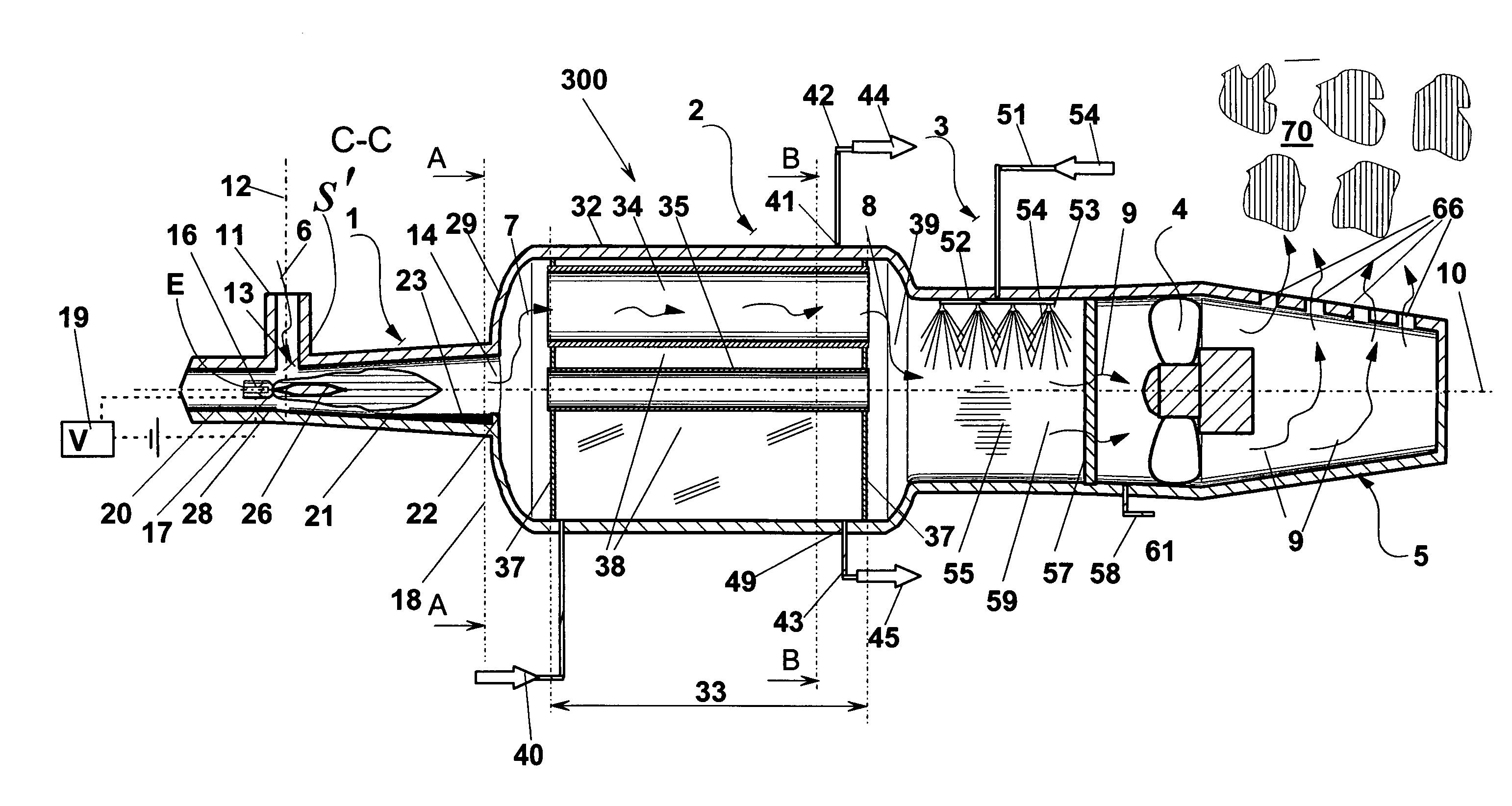
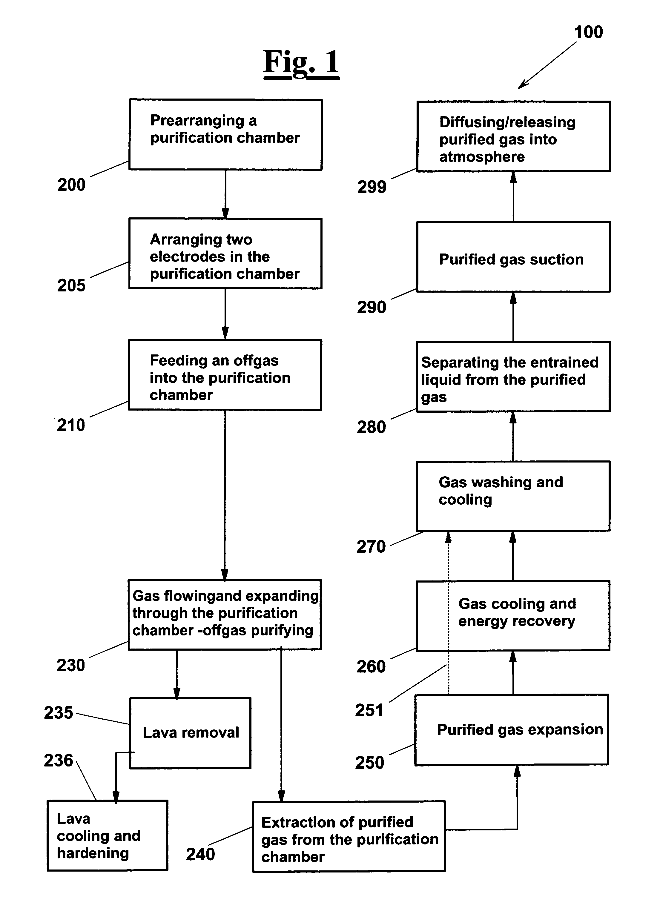
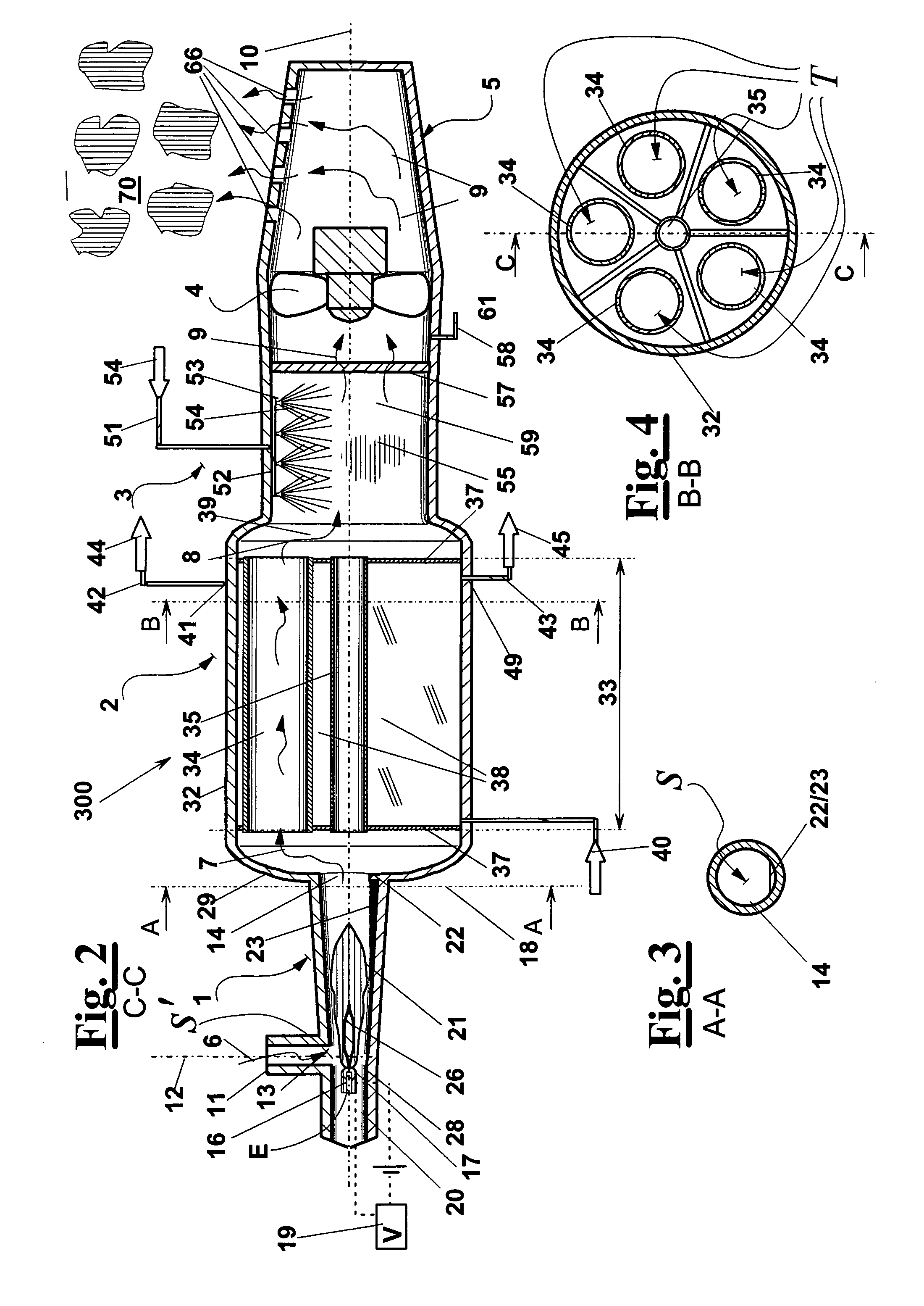
[0081]FIG. 1 shows diagrammatically the method according to the invention, where a step 200 is provided of prearranging a purification chamber 1 (FIG. 6) for treating an offgas 6, and a step 205 of arranging a couple of electrodes 16 in the purification chamber 1, that are connected to a voltage applying means 19. The method provides a step 210 of feeding offgas 6, which flows between electrodes 19 to form a plasma torch 26. Starting from electrodes 16, offgas 6 flows and expands through purification chamber 1 and undergoes a purifying step 230. During step 230, molecular changes take place such that offgas 6 is transformed into:

[0082]a purified gas 7, which consists substantially of oxidation products of the compounds organic that are present in offgas 6, in particular CO2 and steam, possibly together with atmospheric nitrogen and minor amounts of not oxidized or of partially oxidized organic compounds;

[0083]a substantially liquid residue or a lava 23, which is collected and draine...


PUM


Abstract

A plasma method and apparatus for purifying an offgas containing inorganic and organic pollutants. A plasma torch (26) is formed by interaction of the offgas (6) with an electric field (E) created by a voltage (V) applied between one or more couples of electrodes (16) arranged upstream / along a purification chamber (1); the electric field is such that an electric discharge takes place which ionizes the offgas (6) and causes a redistribution of atoms / molecules, thus creating longer molecules, which form a liquid residue (23), and shorter molecules, which form a purified gas (7). The gas undergoes an expansion that is caused by a diverging portion (21) of the purification chamber and assists preliminary cooling of the of fgas / purified gas (6 / 7). A tube-bundle exchanger (2) is provided and has a cross section larger than the outlet port (14) of the chamber to allow further expansion / cooling. A scrubber (3) is arranged downstream exchanger (2).

Description

FIELD OF THE INVENTION[0001]The present invention relates to a method and an apparatus for purifying an offgas that contains various pollutants.[0002]For instance, the method and the apparatus are well suited for treating offgas produced by industrial waste incineration units, where offgas is treated which contains both inorganic and organic pollutants, in particular, particulate matter and heavy metals.BACKGROUND OF THE INVENTION[0003]Many human activities produce offgas, which may contain organic and inorganic pollutants to be eliminated before releasing the offgas into atmosphere.[0004]Organic pollutants are normally destroyed by incineration, whose main limits are a large fuel consumption and the presence of residual, partially oxidized products in the exhaust gas, the combustion temperature being chosen as a compromise between the two problems. Another drawback of is the long transient that is needed to attain a full regime operation of conventional incineration equipment, and ...

Claims


Application Information

Patent Timeline
IPC IPC(8): B03C3/34B03C3/00B03C3/36
CPCB01D53/32B01D53/77B01D2257/60B01D2257/70B01D2259/818Y02E20/363F23G7/063F23J15/04F23J15/06F23J2219/40F23G5/085Y02E20/30
Inventor FABBRI, MARIOSONNO, ENRICO
Owner RE 2
Why Eureka
Try Eureka