Valve timing control apparatus

a timing control and valve technology, applied in mechanical devices, valve arrangements, machines/engines, etc., can solve the problems of reducing the moving speed of the regulation pin, affecting the operation of the valve, and reducing the efficiency of the valve, so as to suppress the leakage of hydraulic fluid, facilitate the introduction of atmosphere, and prevent communication

Active Publication Date: 2011-07-07
DENSO CORP
View PDF19 Cites 25 Cited by
  • Summary
  • Abstract
  • Description
  • Claims
  • Application Information

AI Technical Summary

Benefits of technology

[0024]Note that it is possible to prohibit communication between the communication holes and the opening hole by moving the sub regulation member to the interruption position. Accordingly, in such interruption state, the valve timing can be controlled by the introduction of hydraulic fluid into one of the advance chamber and the retard chamber.
[0025]It may be arranged such that a throttle member to reduce a fluid flow area is provided in a communication passage formed by the movement of the sub regulation member in the insertion direction from...

Problems solved by technology

However, in the apparatus disclosed in Patent Document 1, when the internal combustion engine quickly stops due to occurrence of abnormality, the internal combustion engine might stop before the rotational phase is regulated to the regulation phase by insertion of the regulation pin into the recess part.
However, pressure loss increases upon pushing the remaining hydraulic fluid from the operation chamber esp...

Method used


Image

  • Valve timing control apparatus
  • Valve timing control apparatus
  • Valve timing control apparatus

Examples


first embodiment

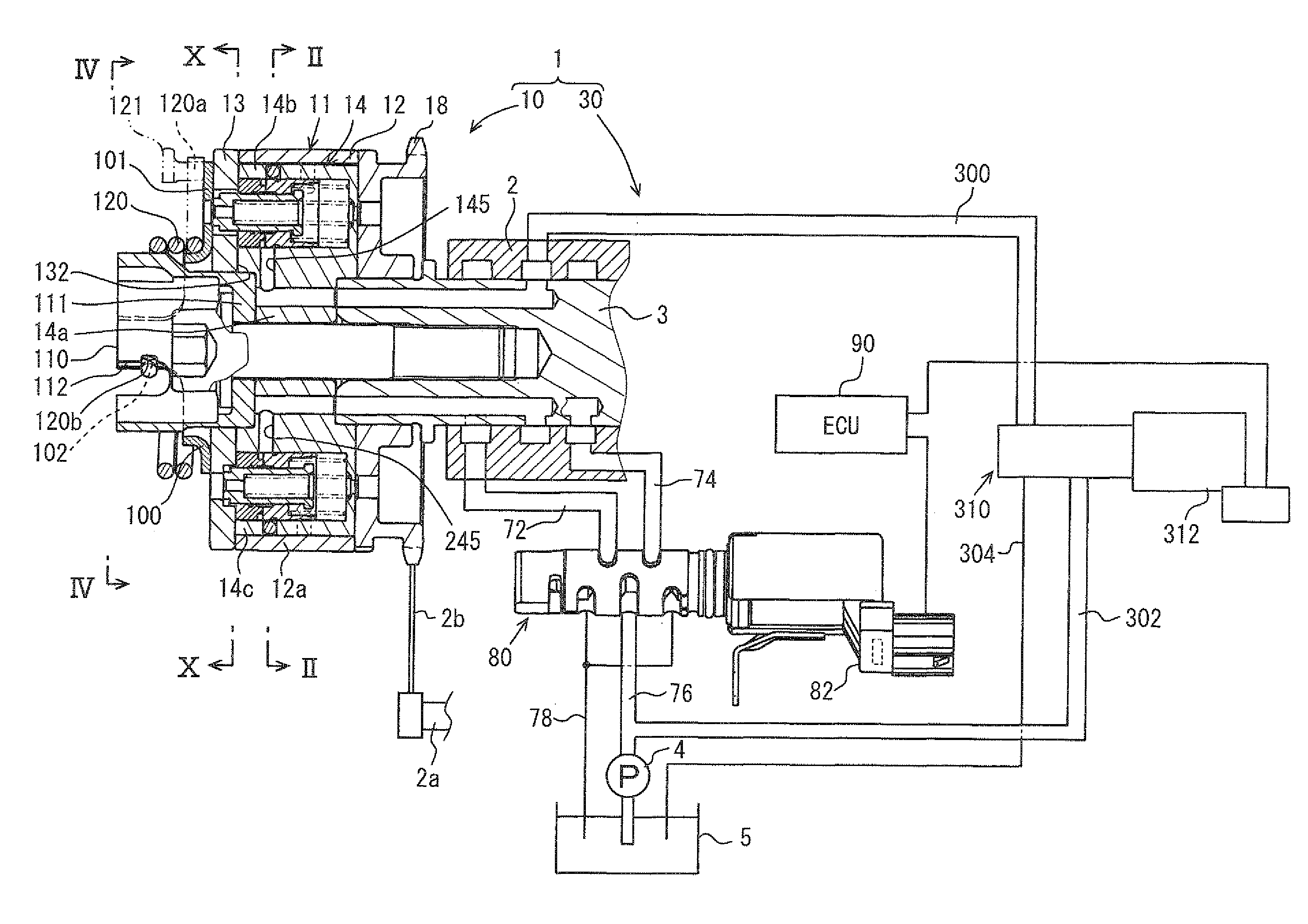
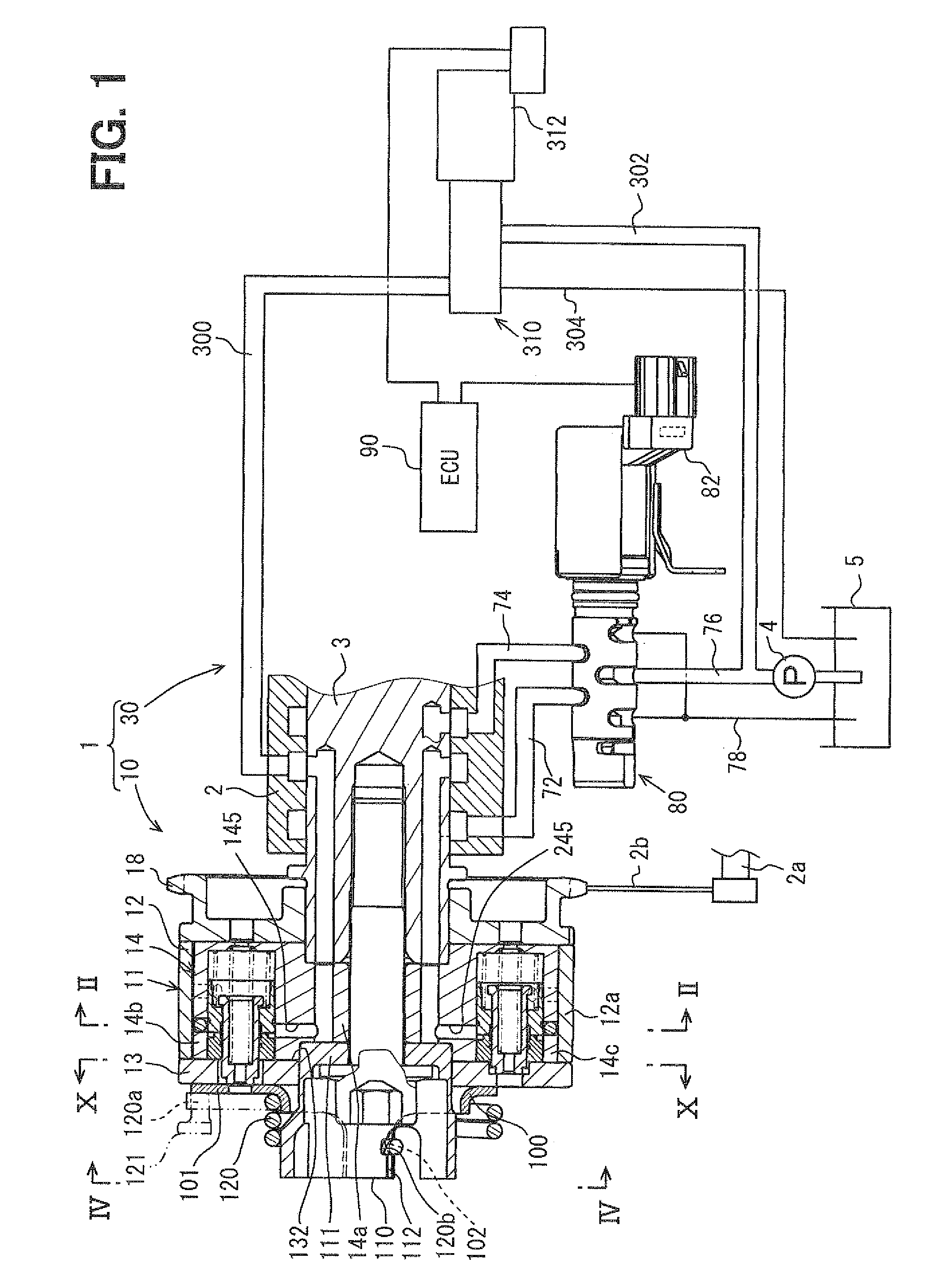
[0084]Hereinbelow, the first embodiment of the present invention will be described based on the drawings. FIG. 1 shows a valve timing control apparatus 1 according to the first embodiment of the present invention. The valve timing control apparatus 1 is applied to a vehicle internal combustion engine 2. The valve timing control apparatus 1 controls valve timing of an intake valve serving as a “drive gear”, which is opened and closed by a camshaft 3, through oil serving as “hydraulic fluid” supplied from a pump 4 serving as a “supply source”.

(Basic Structure)

[0085]Hereinbelow, the basic structure of the valve timing control apparatus 1 will be described. The valve timing control apparatus 1 has a drive unit 10 provided in a transmission system to transmit engine torque from a crankshaft 2a of the internal combustion engine 2 to the camshaft 3, and a control unit 30 to control operation of the drive unit 10.

(Drive Unit)

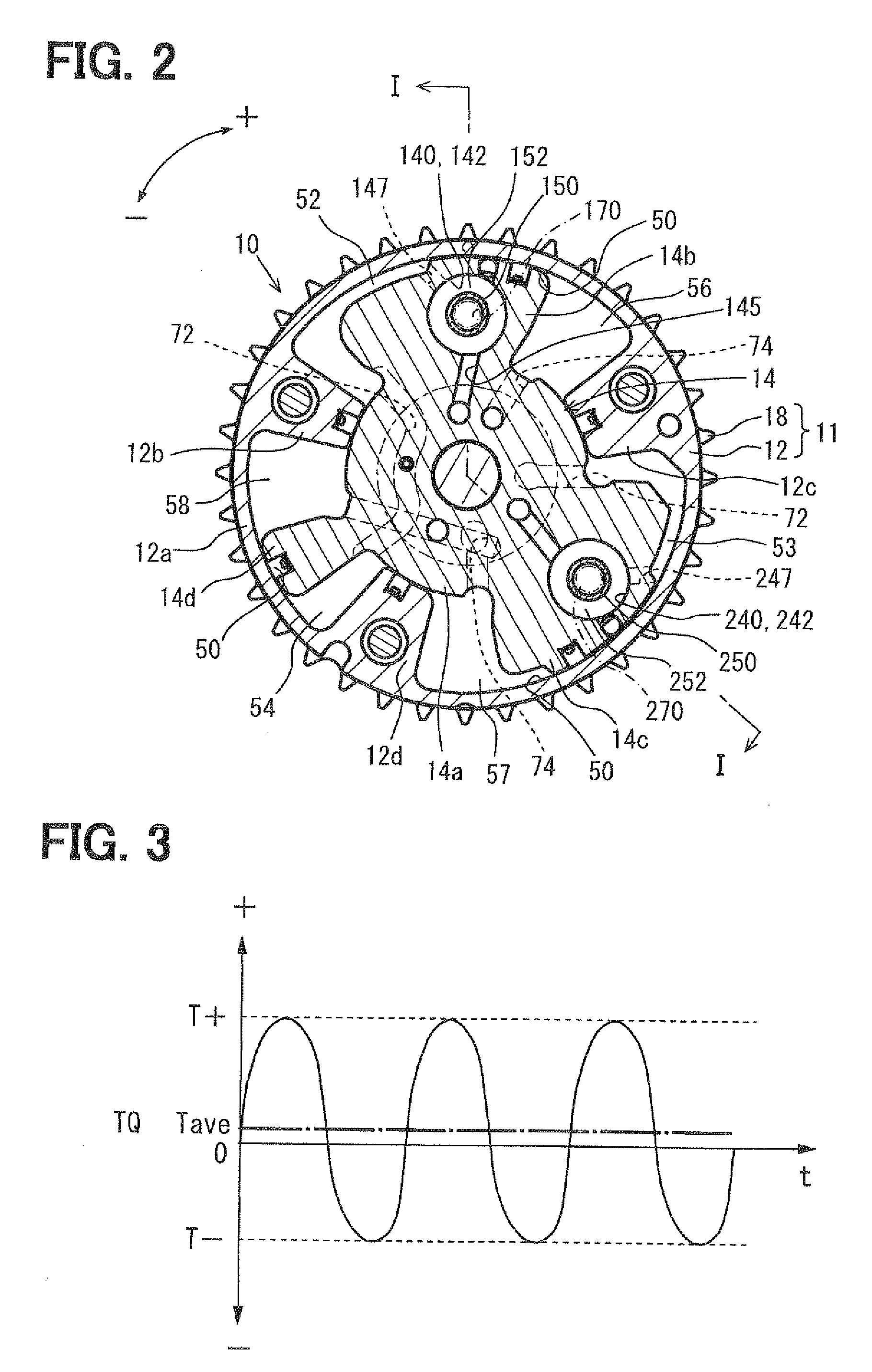
[0086]As shown in FIGS. 1 and 2, a housing 11 has a shoe member 12...

second embodiment

[0179]As shown in FIGS. 22 to 25, the second embodiment of the present invention is a modification of the first embodiment. In the second embodiment, peripheral grooves 2157 and 2257 formed in first and second sub regulation members 2152 and 2252 are not opened to the space located on the side of the first and second sub regulation members 2152 and 2252 opposite from the cover member 13. As a result, communication between the peripheral grooves 2157 and 2257 and the communication chambers 148 and 248 is substantially prohibited. Further, communication between the first and second advance communication holes 147 and 247 and the corresponding communication chambers 148 and 248 is substantially prohibited by the first and second sub regulation members 2152 and 2252 at any positions. Further, communication between first and second retard communication holes 2147 and 2247 and the corresponding communication chambers 148 and 248 is substantially prohibited by the first and second sub regu...

third embodiment

[0184]As shown in FIGS. 26 to 29, a third embodiment of the present invention is a modification of the second embodiment. In the third embodiment, atmospheric holes 3137 and 32367 which are always atmospherically opened and which always communicate with the communication chambers 148 and 248 respectively communicate with the first and second through holes 149 and 249 in the entire region of the rotational phase including the lock phase.

[0185]Further, the first and second sub regulation members 3152 and 3252 of the third embodiment form multiple first and second ventilation passages 3160 and 3260 in cylindrical hole shape through the bottoms of the peripheral grooves 2157 and 2257 in a radial direction to communicate the peripheral grooves 2157 and 2257 with the communication chambers 148 and 248 respectively in a circumferential direction. Note that the first and second advance communication holes 147 and 247 and the first and second retard communication holes 2147 and 2247 face and...


PUM


Abstract

A valve timing control apparatus has a regulation member to fix a phase. The regulation member has a main regulation member and a sub regulation member. The main regulation member is inserted into a recess part to regulate the phase. The sub regulation member has an engagement part engageable with the main regulation member in an escape direction Y and disengageable from the main regulation member in an insertion direction X. Further, the sub regulation member has a pressure reception part that receives pressure in the escape direction Y from hydraulic fluid in an operation chamber. The main regulation member is urged in the insertion direction X by a main resilient member. Further, the sub regulation member is urged in the insertion direction X by a sub resilient member. The main regulation member moves in the escape direction Y only by hydraulic fluid, and moves in the insertion direction X only by the resilient member.

Description

CROSS REFERENCE OF THE RELATED APPLICATION[0001]This application is based upon and claims the benefit of priority from the prior Japanese Patent Application Nos. 2008-233912, filed on Sep. 11, 2008, 2009-106873 filed on Apr. 24, 2009, and 2009-193566 filed on Aug. 24, 2009, the entire contents of which are incorporated herein by reference.TECHNICAL FIELD[0002]The present invention relates to a valve timing control apparatus to control valve timing in an internal combustion engine.BACKGROUND ART[0003]Conventionally, a valve timing control apparatus, which has a housing that is rotatable synchronously with a crankshaft and a vane rotor that is rotatable synchronously with a camshaft, is known to control valve timing with hydraulic fluid supplied from a supply source, such as a pump, in accordance with rotation of an internal combustion engine. For example, in an apparatus disclosed in Patent Document 1, valve timing is controlled by varying a rotational phase of a vane rotor with resp...

Claims


Application Information

Patent Timeline
IPC IPC(8): F01L1/344
CPCF01L1/3442F01L2001/34466F01L1/344F01L2001/34473F01L2001/34483F01L2001/34469F01L2001/34423F01L2001/3445
Inventor FUJIYOSHI, TOSHIKIYAMAGUCHI, TAKASHI
Owner DENSO CORP
Why Eureka
Try Eureka