Biological image acquisition device
- Summary
- Abstract
- Description
- Claims
- Application Information
AI Technical Summary
Benefits of technology
Problems solved by technology
Method used
Image

Examples
embodiment 1
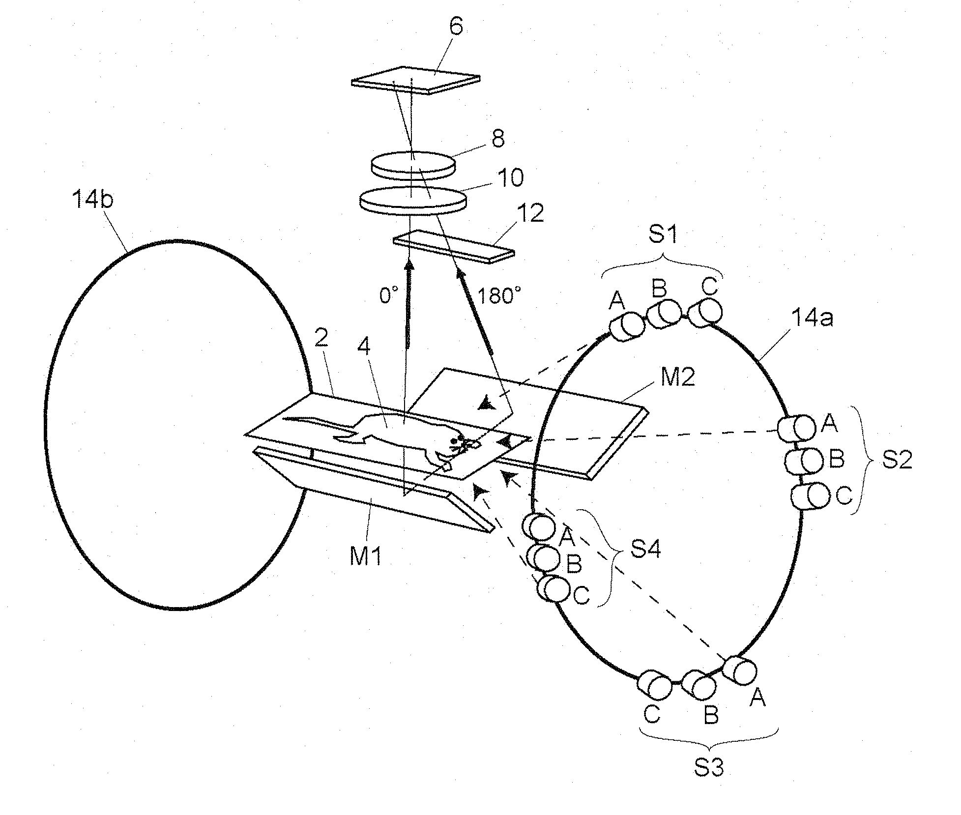
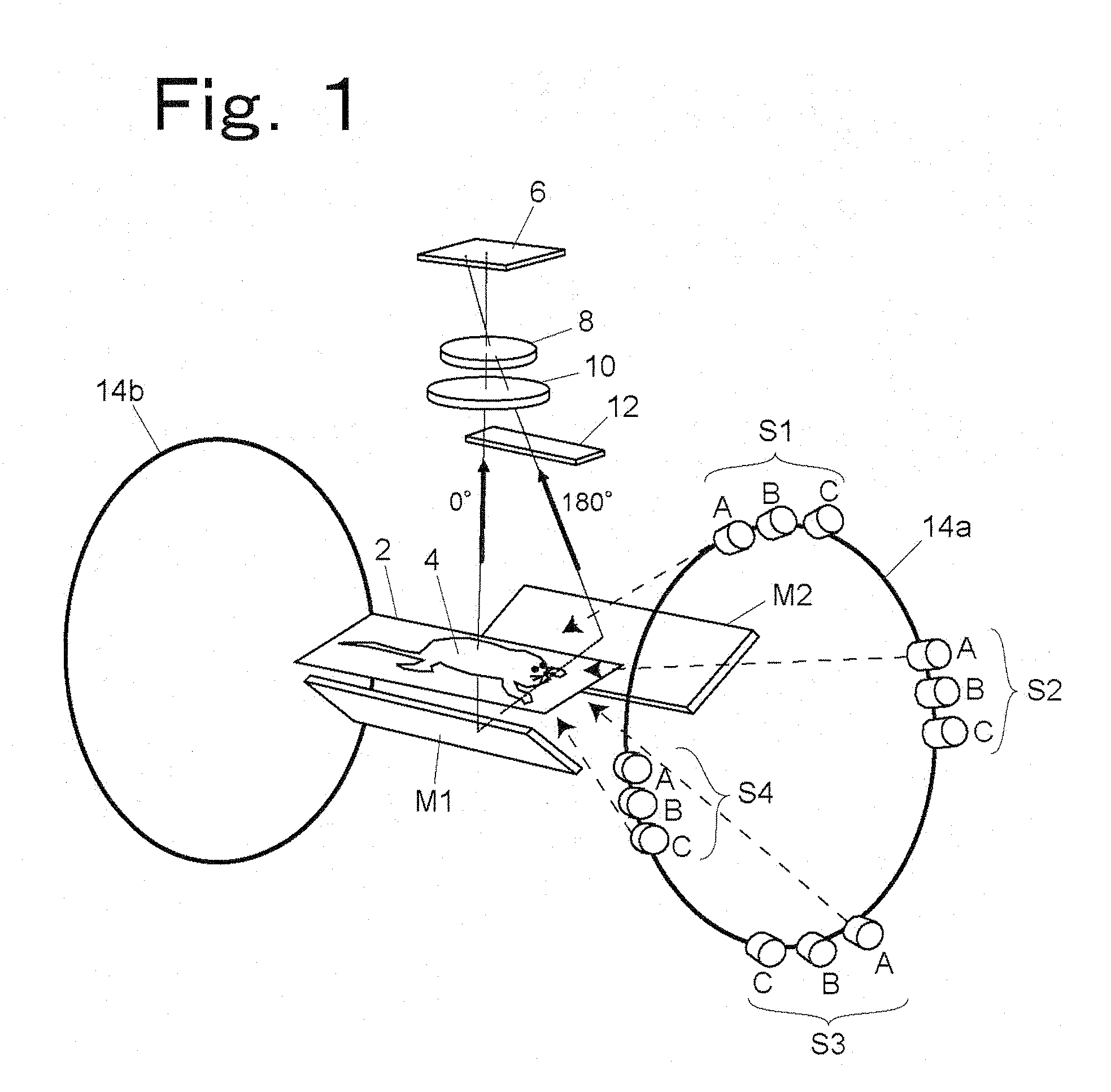
One embodiment of a biological image acquisition device according to the present invention will be described as follows. FIG. 1 is a schematic view showing the structure of an embodiment of a device capable of observing a biological specimen from two directions, from above and below.
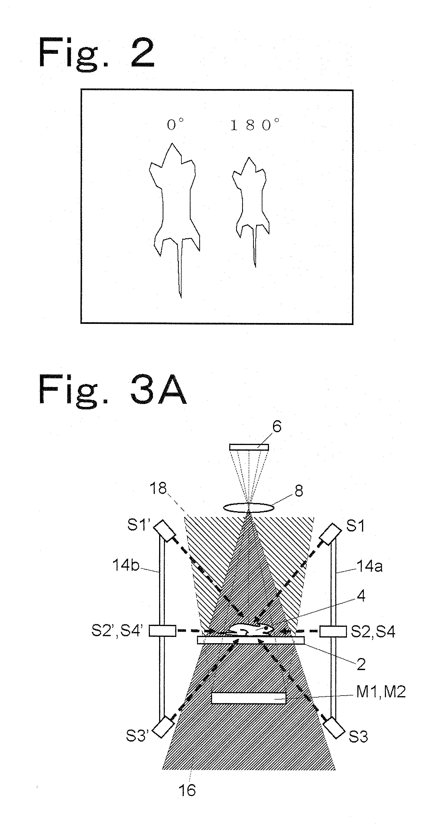
A biological specimen (small animal) 4 is placed on a transparent specimen support 2. A two-dimensional detector 6 such as a CCD camera is arranged directly above the biological specimen 4. A main image forming lens 8 is arranged on the detection surface-side of the two-dimensional detector 6. If necessary, a fluorescence-side filter 10, which transmits only a fluorescence component emitted from the biological specimen 4, is arranged between the main image forming lens 8 and the biological specimen 4. Reflectors M1 and M2 for leading the light of back-side (180° direction) image of the biological specimen 4 to the main image forming lens 8 are arranged on the lower side of the specimen support 2.
A light ...
embodiment 2
An embodiment of a biological image acquisition device capable of simultaneously picking up images of a biological specimen from five directions will be described. FIG. 5 is a schematic view showing the structure of an embodiment of a biological image acquisition device capable of simultaneously observing a biological specimen from five directions.
The biological specimen (small animal) 4 is placed on the transparent specimen support 2. The two-dimensional detector 6, such as a CCD camera, is arranged directly above the biological specimen 4. The main image forming lens 8 is arranged on the detection surface-side of the two-dimensional detector 6. If necessary, the fluorescence-side filter 10, which transmits only a fluorescence component emitted from the biological specimen 4, is arranged between the main image forming lens 8 and the biological specimen 4. Reflectors M2, M3, M4, and M5 are arranged counterclockwise around the specimen support 2. The reflection mirrors M2 to M5 refle...
embodiment 3
An embodiment using concave mirrors as reflection mirrors will be described with reference to FIGS. 12 to 15.
FIG. 12 is a perspective view of an embodiment that is the same as the first embodiment shown in FIGS. 1, 3A, and 3B except that the plane mirrors M1 and M2 are changed to concave mirrors. In this case, it is important that the center of curvature of the concave mirror M1 is set to a position C1 (represented by a black spot in FIG. 12) beside the abdomen of the specimen 4. The position C1 is at the same distance from the lens 8 as the specimen. Therefore, a diagonally bottom left-side image of the specimen as seen from the head-side of the specimen is formed at a position A4 adjacent to the specimen 4 by reflection from the concave mirror M1. Likewise, the center of curvature of the concave mirror M2 is set to a position C2 that is at the same distance from the lens 8 as the specimen. This makes it possible to form a diagonally bottom right-side image of the specimen at a pos...
PUM
 Abstract
Description
Claims
Application Information
 - Generate Ideas
- Intellectual Property
- Life Sciences
- Materials
- Tech Scout
- Unparalleled Data Quality
- Higher Quality Content
- 60% Fewer Hallucinations
Browse by: Latest US Patents, China's latest patents, Technical Efficacy Thesaurus, Application Domain, Technology Topic, Popular Technical Reports.
© 2025 PatSnap. All rights reserved.Legal|Privacy policy|Modern Slavery Act Transparency Statement|Sitemap|About US| Contact US: help@patsnap.com