Laser module co-axis adjustment structure

Inactive Publication Date: 2011-07-14
HUANG HSIEN JUNG +1
View PDF16 Cites 18 Cited by
  • Summary
  • Abstract
  • Description
  • Claims
  • Application Information

AI Technical Summary

Benefits of technology

[0009]The present invention has been accomplished under the circumstances in view. It is therefore the main object of the present invention to provide a laser module co-axis adjustment structure, which has small size and high precision characteristics. It is another object of the present invention to provide a laser module co-axis adjustment structure, which facilitates calibration of the alignment of the optical axis.
[0010]To achieve these and other objects of the present invention, a laser module co-axis adjustment structure comprises a laser module and an eccentric sleeve. The laser module comprises a hollow casing, an optical module mounted inside the hollow casing, a circuit board, a laser diode electrically soldered to the circuit board and controlled by the circuit board to emit a laser beam through the optical module. The eccentric sleeve is movably sleeved onto the hollow casing of the laser module and rotatable relative to the hollow casing through 360-degrees. The eccentric sleeve has an eccentrically disposed inside sloping surface stopped against the periphery of the hollow casing of the laser module for enabling the eccentric sleeve to be rotated relative to the laser module to adjust the mechanical axis of the eccentric sleeve into alignment with the optical axis of the optical module of the laser module.
[0011]Further, the hollow casing of the laser module has an outer thread. Further, the eccentric sleeve has an inner thread threaded onto the outer thread of the hollow casing of the laser module, facilitating stable and accurate rotation of the eccentric sleeve relative to the laser module during calibration.

Problems solved by technology

However, few manufacturers make improvement on the quality of the spot or line of light generated.
Because regular laser modules are small-sized products, it is difficult to adjust the laser diode and the optical lens system into perfect alignment.
These conventional laser modules cannot satisfy consumers' strict quality requirements.
Using these conventional laser modules does not provide satisfactory effects (the problem will become worse if it is used for a long distance application), lowering the added value.
The use of these copper or aluminum members complicates the assembly process.
During installation, it is difficult to keep the optical axis in perfect alignment with the mechanical axis.
However, because the barrel A is a small-sized member, tapping the screw holes A2 on the barrel A may damage the structure or lower the strength of the barrel A. To avoid this problem, the barrel A must have a certain wall thickness.
However, increasing the wall thickness of the barrel
A will relatively increase the dimension of the barrel A. Therefore, this design of laser diode co-axis adjustment structure does not meet small size and high precision requirements.

Method used


Image

  • Laser module co-axis adjustment structure
  • Laser module co-axis adjustment structure
  • Laser module co-axis adjustment structure

Examples


Embodiment Construction

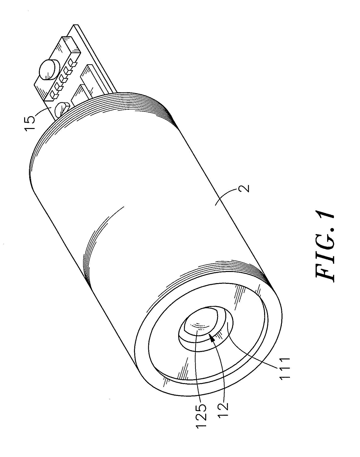
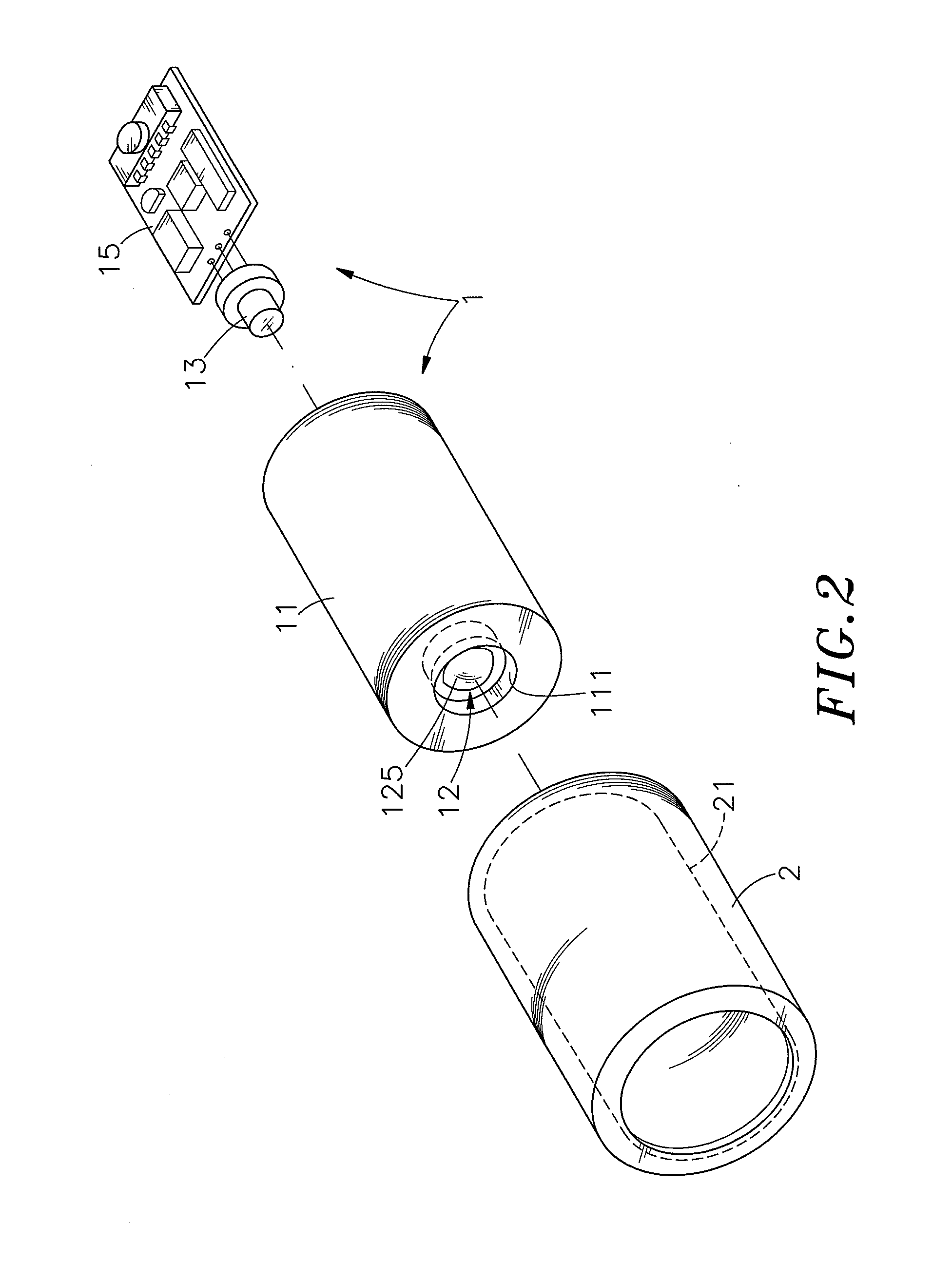
[0021]Referring to FIGS. 1-4, a laser module co-axis adjustment structure in accordance with the present invention is shown comprising a laser module 1 and an eccentric sleeve 2.

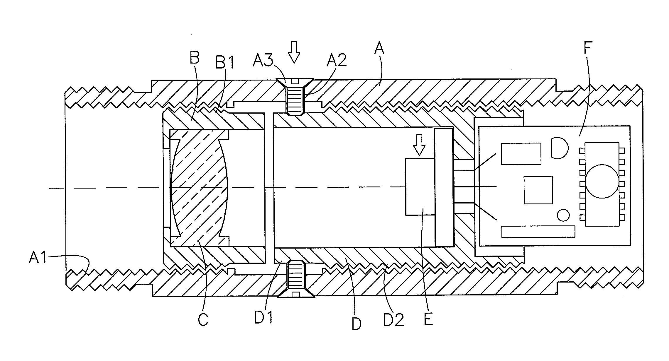
[0022]The laser module 1 comprises a hollow cylindrical casing 11, an optical module 12, a laser diode 13, a photovoltaic diode 14 and a circuit board 15. The hollow cylindrical casing 11 houses the optical module 12, the laser diode 13 and the photovoltaic diode 14.

[0023]The laser diode 13 and the photovoltaic diode 14 are electrically soldered to the circuit board 15 that is disposed at the rear side of the hollow cylindrical casing 11. The optical module 12 is mounted inside the hollow cylindrical casing 11 in axial alignment with a front projection hole 111 of the hollow cylindrical casing 11. The laser diode 13 operates in the wavelength within 800-820 nm. Further, the optical module 12 comprises a focus lens 121, a crystal component set 122, a beam splitter 123, a bi-concave lens 124 and a lens 125. Wh...


PUM


Abstract

A laser module co-axis adjustment structure includes a laser module that includes an optical module and a laser diode housed inside a hollow casing and a circuit board for controlling the laser diode to emit a laser beam through the optical module, and an eccentric sleeve, which is rotatable relative to the casing through 360-degrees and has an eccentrically disposed inside sloping surface stopped against the periphery of the hollow casing of the laser module for enabling the eccentric sleeve to be rotated relative to the laser module to adjust the mechanical axis of the eccentric sleeve into alignment with the optical axis of the optical module of the laser module. The eccentric sleeve and the hollow casing may be affixed with an adhesive after calibration of the alignment.

Description

[0001]This application claims the priority benefit of Taiwan patent application number 099200671, filed on Jan. 13, 2010.BACKGROUND OF THE INVENTION[0002]1. Field of the Invention[0003]The present invention relates to laser module technology and more particularly, to a laser module co-axis adjustment structure, which allows calibration of the alignment of the optical axis by means of rotating an eccentric sleeve through 360-degrees relative to the laser module.[0004]2. Description of the Related Art[0005]Visible light (red or green) laser modules are intensively used in pointing devices, aiming device, level tools, line laser markers. These conventional laser module designs have appeared on the market for years. However, few manufacturers make improvement on the quality of the spot or line of light generated. Because regular laser modules are small-sized products, it is difficult to adjust the laser diode and the optical lens system into perfect alignment. If the laser diode and the...

Claims


Application Information

Patent Timeline
IPC IPC(8): G01B11/00
CPCH01S5/005H01S5/0683H01S5/042H01S5/02288H01S5/02253
Inventor HUANG, HSIEN-JUNG
Owner HUANG HSIEN JUNG
Why Eureka
Try Eureka