
Engine valve for improved operating efficiency

Inactive Publication Date: 2011-07-14
KERR JAY CARL
View PDF13 Cites 4 Cited by
  • Summary
  • Abstract
  • Description
  • Claims
  • Application Information

AI Technical Summary

Benefits of technology

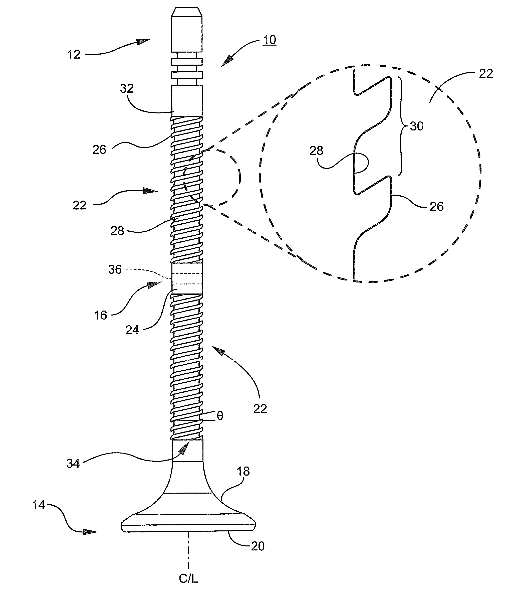
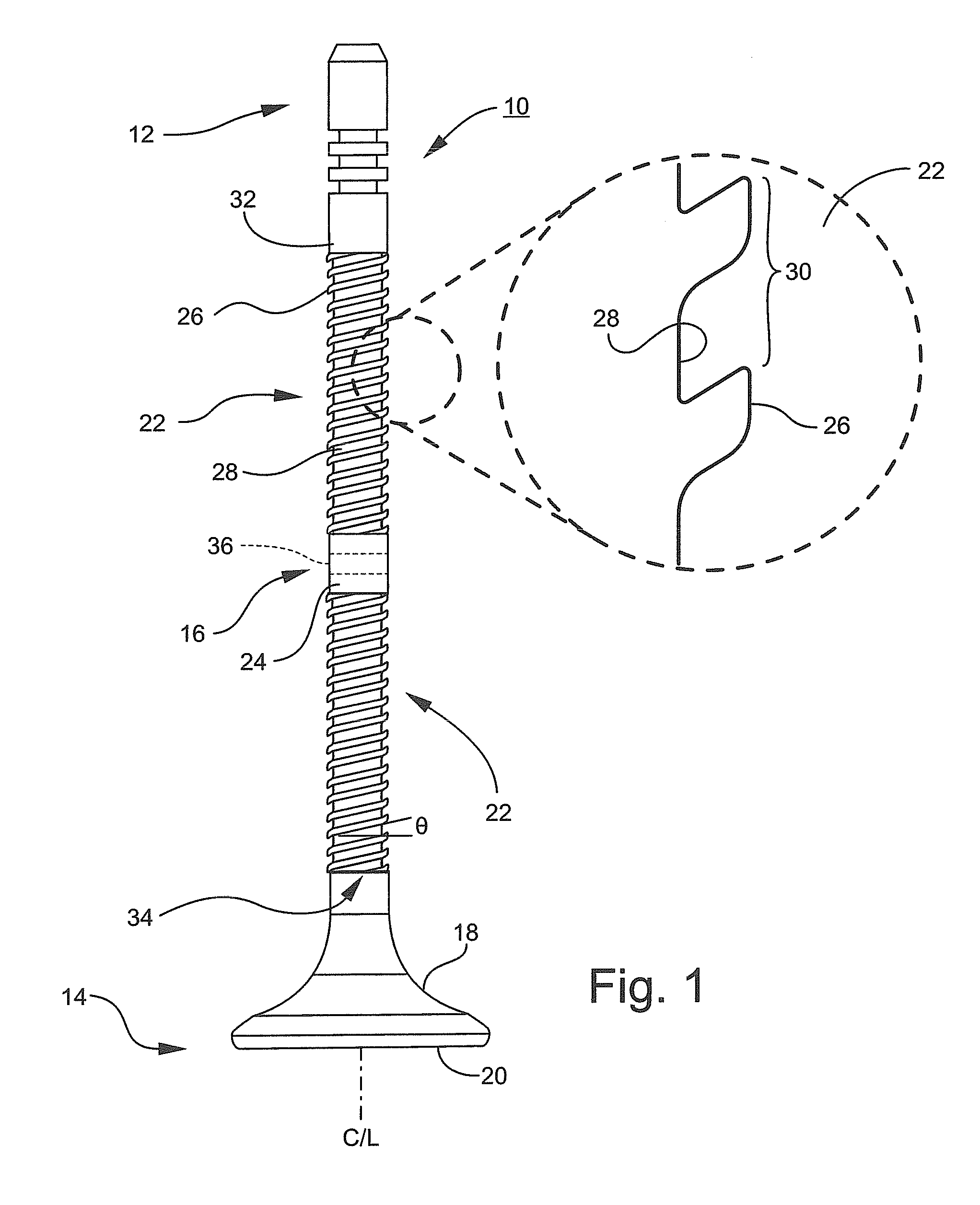
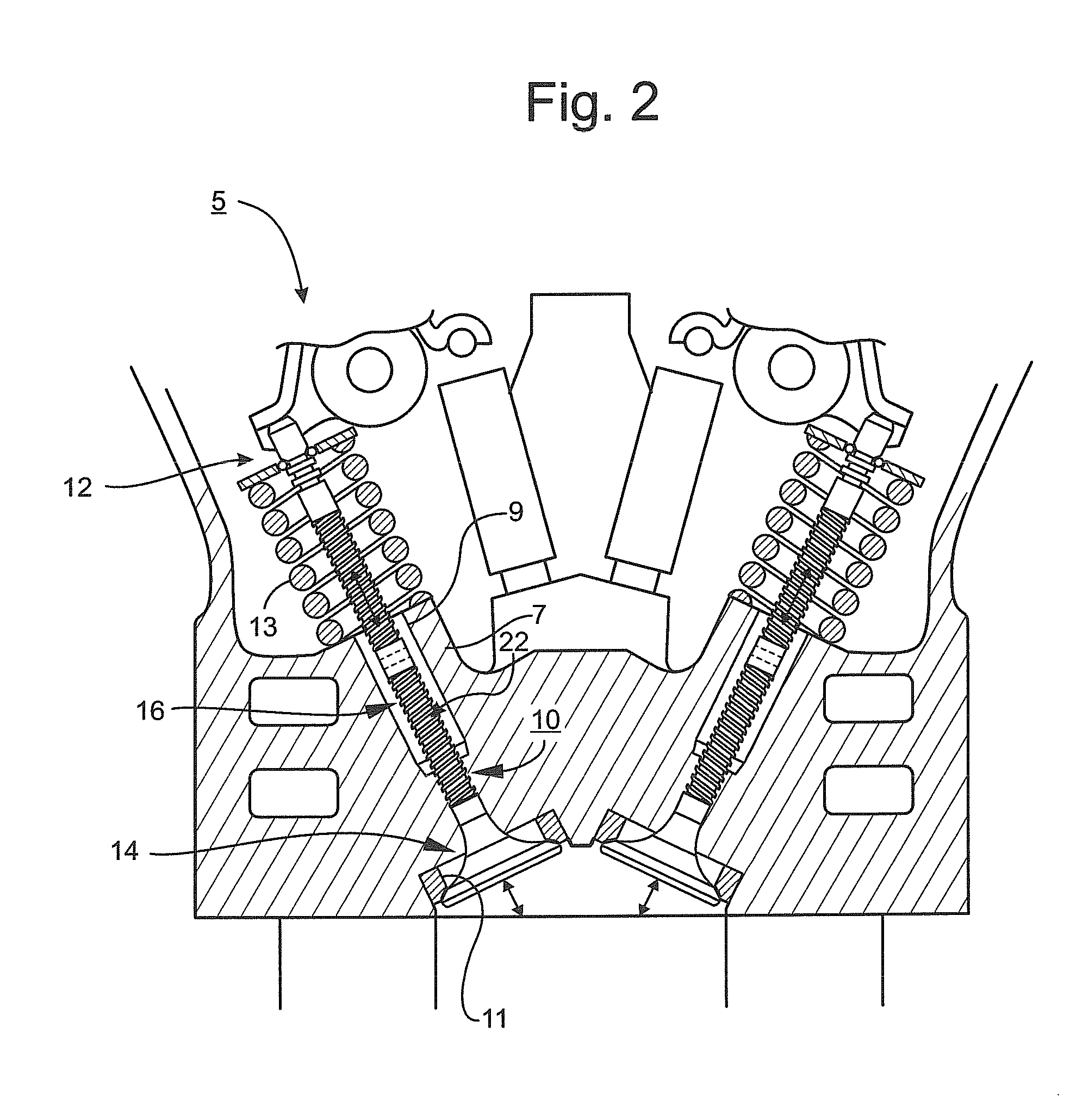
[0004]The present disclosure is directed in general to a valve for improving efficiency in engines of various types, including but not limited to automobiles, trucks, farm equipment, motorcycles, boats, lawn and garden equipment, and the like. The engine valve broadly includes a solid valve stem having a helical groove inscribed into the stem or material ablated from the stem to form the helical groove. In operation, the helical groove reduces mass and frictional area of the valve to improve overall engine operating efficiency.
[0009]In yet a further embodiment, an engine valve may include a valve head; a tip portion disposed opposite of the valve head; and a stem interposed between the valve head and the tip portion, the stem having a helical groove adapted to move the engine valve from a first position to a second position under a reduced valve seat load to reduce a parasitic loss in engine function. In this example, the helical groove may have at least two crests and one root interposed between the two crests. Further, the helical groove may have more than one start.
[0011]In a further aspect, a method may be provided to reduce contact area of a valve in an engine to reduce valve seat load, to reduce valve spring load, to increase air-fuel mixture under a seat of the valve, and to reduce lifter and camshaft load. The method may include reducing a mass of a valve by forming a helical portion about a stem of the valve; installing the valve in a cylinder head of an engine; and increasing engine efficiency by reducing a coefficient of drag of the valve, wherein the helical portion is configured to have reduced surface contact in the engine. The helical portion according to this method may have one or more starts. Further, the mass removed in this exemplary method may be between about twenty percent to about twenty-five percent of a diameter of the stem.

Problems solved by technology

Although material modifications may succeed in reducing the weight of an engine valve, some engine valves, such as those having ceramic valve heads, wear out more quickly from repetitive contact against respective valve seats.
However, torque, tension, pressure and other forces may greatly wear on a joint between a metal valve head and its lightweight valve stem to limit the life of the composite engine valve prematurely.

Method used


Image

  • Engine valve for improved operating efficiency
  • Engine valve for improved operating efficiency
  • Engine valve for improved operating efficiency

Examples


Embodiment Construction

[0018]Detailed reference will now be made to the drawings in which examples embodying the present subject matter are shown. The detailed description uses numerical and letter designations to refer to features of the drawings. Like or similar designations of the drawings and description have been used to refer to like or similar parts of various exemplary embodiments.

[0019]The drawings and detailed description provide a full and written description of the present subject matter, and of the manner and process of making and using various exemplary embodiments, so as to enable one skilled in the pertinent art to make and use them, as well as the best mode of carrying out the exemplary embodiments. However, the examples set forth in the drawings and detailed description are provided by way of explanation only and are not meant as limitations of the disclosure. The present subject matter thus includes any modifications and variations of the following examples as come within the scope of t...


PUM


Abstract

An engine valve is provided with a valve head, a cap disposed opposite of the valve head; and a stem interposed between the valve head and the cap. The stem has a cylindrically shaped surface and at least one helical section embedded in the stem. The helical section includes alternating crests and roots in which the roots depend inwardly in a direction of a centerline of the valve such that the surface area of the stem is periodically interrupted by the helical section. The introduction of the valve with helical section in an engine increases engine efficiency and reduces fuel consumption. Methods of making and using the engine valve are also provided.

Description

BACKGROUND OF THE DISCLOSURE[0001]By improving operating efficiency of an internal combustion engine, fuel efficiency is also improved so that the engine requires less fuel over its operating life. To improve engine efficiency, lightweight materials can be used to manufacture component parts of an engine, including intake and exhaust valves. Even if no other engine component is modified, lightweight engine valves alone can increase engine performance and greatly reduce fuel consumption.[0002]Lightweight engine valves are known that are constructed from ceramic materials, titanium aluminum alloys, as well as thermoplastics. Although material modifications may succeed in reducing the weight of an engine valve, some engine valves, such as those having ceramic valve heads, wear out more quickly from repetitive contact against respective valve seats. To increase valve service life, some composite engine valves employ metal alloy valve heads with valve stems of lightweight material. Howev...

Claims


Application Information

Patent Timeline
IPC IPC(8): F01L3/20
CPCF01L3/205
Inventor KERR, JAY CARL
Owner KERR JAY CARL
Learn More