Land Based and Pontoon Based Forced Air Thermal Evaporator

a forced air thermal evaporator and pontoon technology, applied in the field of evaporation systems, can solve the problems of more rapid evaporation than other problems, and achieve the effects of reducing environmental impact, reducing environmental impact, and reducing evaporation ra

Inactive Publication Date: 2011-07-14
TAFOYA JAMES
View PDF14 Cites 23 Cited by
  • Summary
  • Abstract
  • Description
  • Claims
  • Application Information

AI Technical Summary

Benefits of technology

[0025]The system allows for a greater evaporation rate by utilizing waste heat to form a water / steam vapor to enter the atmosphere. This provides a 65 to 80% greater efficiency over conventional evaporation systems.
[0026]This system reduces the environmental impact due to the fact that there are no large water droplets for the wind to carry outside containment areas since the water leaving the spiral cones are a fine heated vapor.
[0027]This system enhances the ability to evaporate in cold and humid conditions due to the fact that the water and air are heated using the waste heat source. The system is modular so that is can be customized for size and evaporation needs at each site.

Problems solved by technology

When the system rotates, water exits, sprayed by the spraying devices, with the result that evaporation takes place more rapidly than would be the case naturally, owing to the increase in aqueous surface exposed to the air and to the action of the wind.

Method used


Image

  • Land Based and Pontoon Based Forced Air Thermal Evaporator
  • Land Based and Pontoon Based Forced Air Thermal Evaporator
  • Land Based and Pontoon Based Forced Air Thermal Evaporator

Examples


Embodiment Construction

[0073]The following discussion describes in detail one embodiment of the invention (and several variations of that embodiment). This discussion should not be construed, however, as limiting the invention to those particular embodiments, practitioners skilled in the art will recognize numerous other embodiments as well. For definition of the complete scope of the invention, the reader is directed to appended claims.

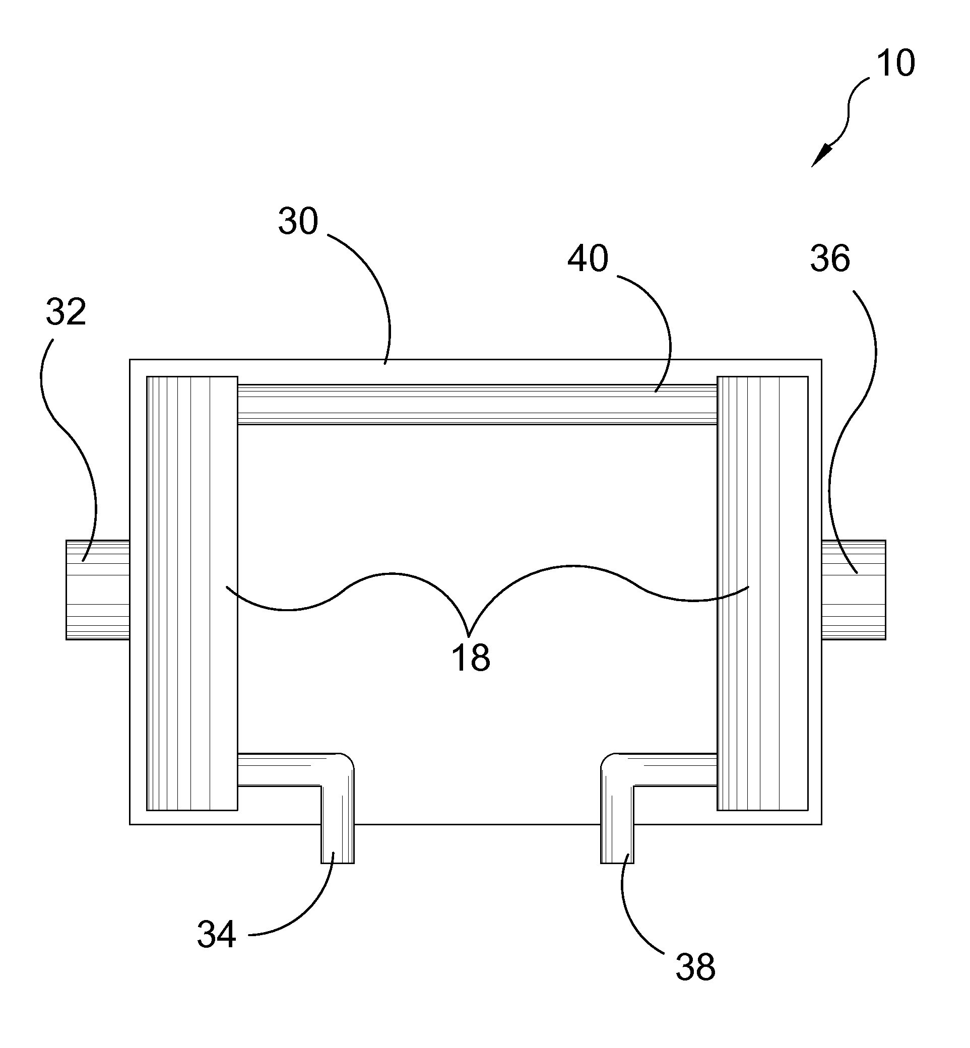
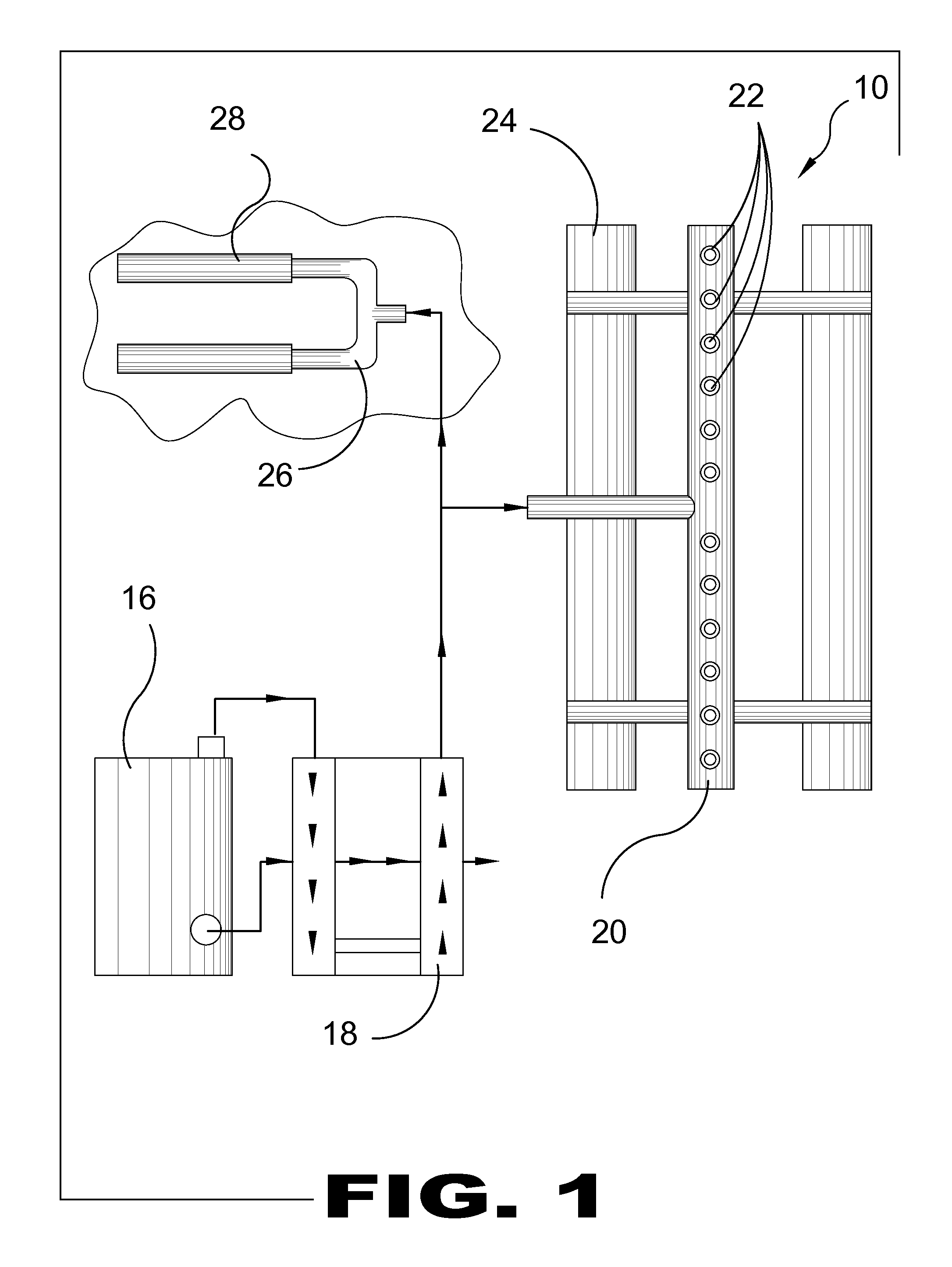
[0074]FIG. 1 is a flow diagram of both embodiments of the evaporation system 10. The present invention is a land based and pontoon based forced air thermal evaporator 10. Shown is the waste exhaust heat 12 used to heat the outgoing air 14 from the air compressor 16 through an air to air heat exchanger 18 to the distribution header 20 in which the air / water mixture is disbursed into the atmosphere through the spiral cone nozzles 22. Also shown are the pontoons 24, the eductor 26 and the discharge pipe 28.

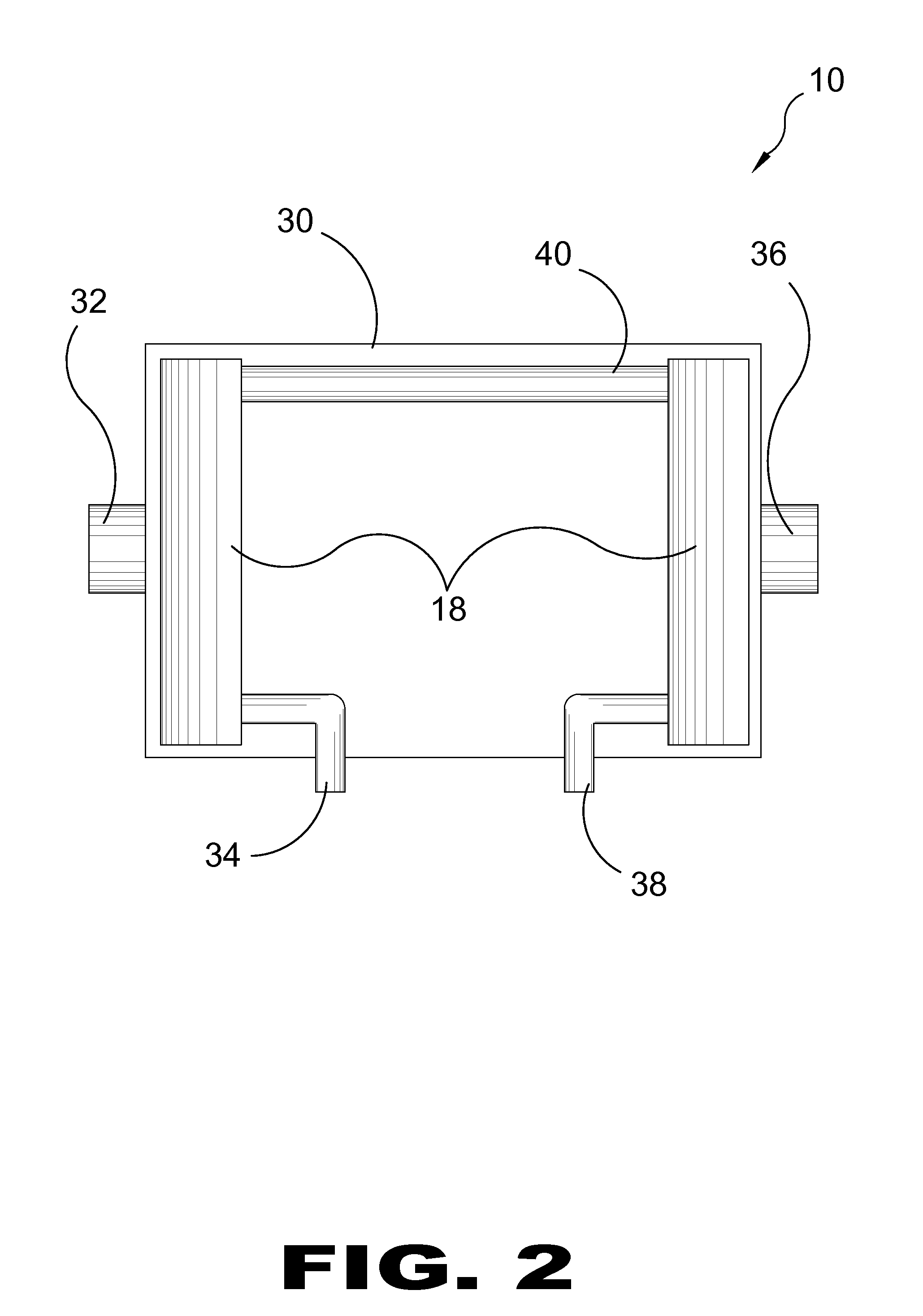
[0075]FIG. 2 is a top view of the primary heat exchanger 18 of the pre...


PUM

PropertyMeasurementUnit
heataaaaaaaaaa
forceaaaaaaaaaa
sizesaaaaaaaaaa

Abstract

A method of evaporating waste water utilizing waste heat employs a forced air thermal evaporator system having an air heat exchanger with: a waste heat inlet, a waste heat outlet, a cold air inlet and a hot air outlet; a compressor connected with the cold air inlet to force air into the cold air inlet; and a distribution header having a hot air inlet connected with the hot air outlet, a waste water inlet connected to a waste water source, and air/water mixing nozzles connected with the hot air inlet and the waste water inlet. Engaging the compressor forces air through the heat exchanger and into the distribution header where the waste water is admixed with the hot air which then exits through spray nozzles as water vapor.

Description

BACKGROUND OF THE INVENTION[0001]1. Field of the Invention[0002]The present invention relates generally to evaporation systems and, more specifically, to a water evaporation system for use in disposing of wastewater in the mining, manufacturing, oil and gas and food processing industries. Depicted in the application drawings are dimensioned embodiments for illustrative purposes only of the components of the present invention and should not be taken as the only possible sizes envisioned by the instant invention.[0003]One or more modular nozzle systems float on water source or sit away from water source. For pontoon based system each nozzle system has a series of nozzles that sit on a riser that is attached to inlet air source or for land based has two nozzles mounted on a stand that is attached to inlet air source. Air is pumped through a primary heat exchanger to inlet air distribution header and through nozzles, which draws water into the air / water mixing nozzles to emit small wate...

Claims


Application Information

Patent Timeline
Patent Type & Authority Applications(United States)
IPC IPC(8): C02F1/04
CPCB01D1/0094C02F1/12C02F1/048B01D1/14
Inventor TAFOYA, JAMES
Owner TAFOYA JAMES
Why Eureka
Try Eureka