

Composite magnetic material and magnetic element
a magnetic material and composite technology, applied in the field of composite magnetic material and magnetic element, can solve the problems of increasing core loss, increasing core loss, increasing core loss, etc., and achieves excellent characteristics, high rust proof performance of magnetic element, and stable electrical characteristics.
- Summary
- Abstract
- Description
- Claims
- Application Information
AI Technical Summary
Benefits of technology
Problems solved by technology
Method used
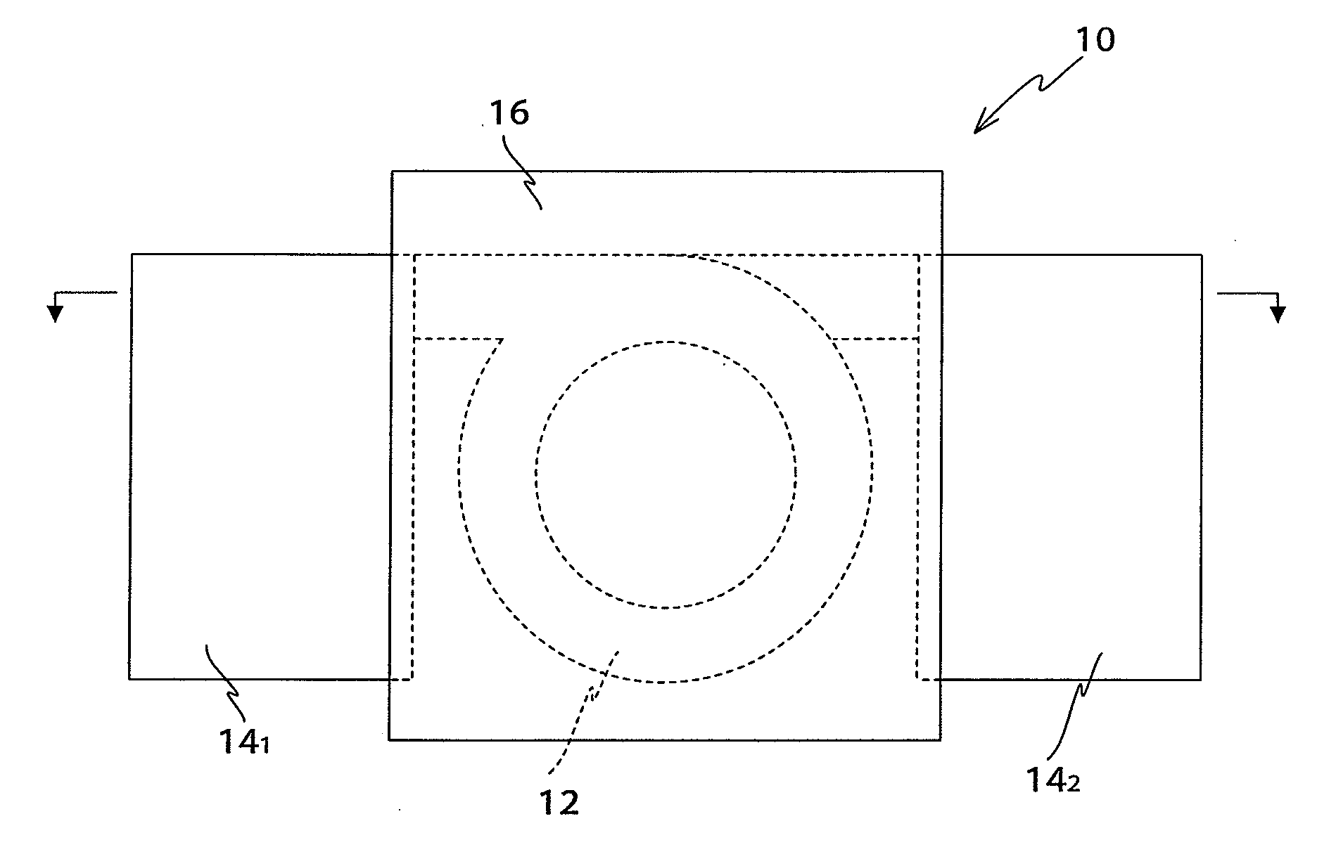
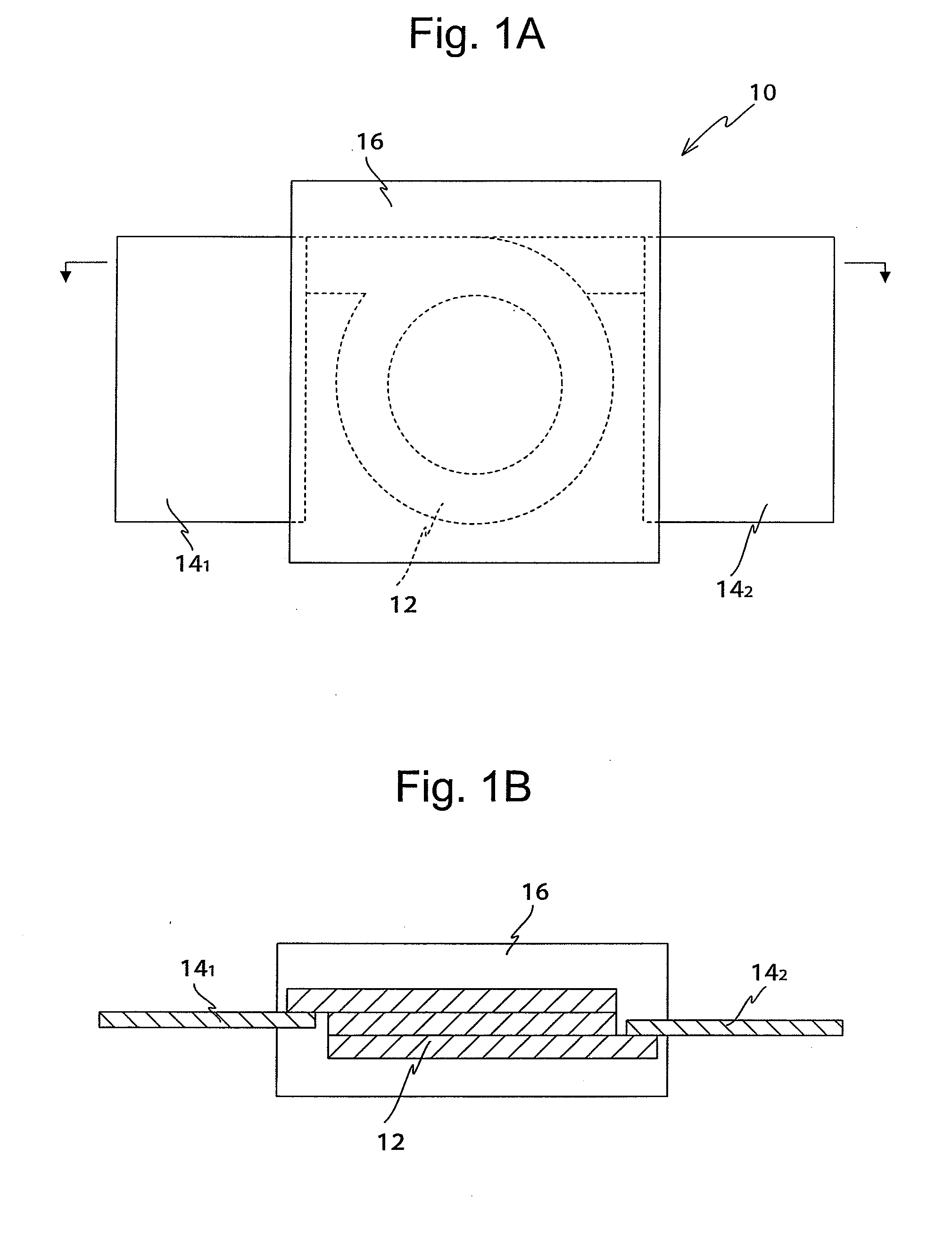
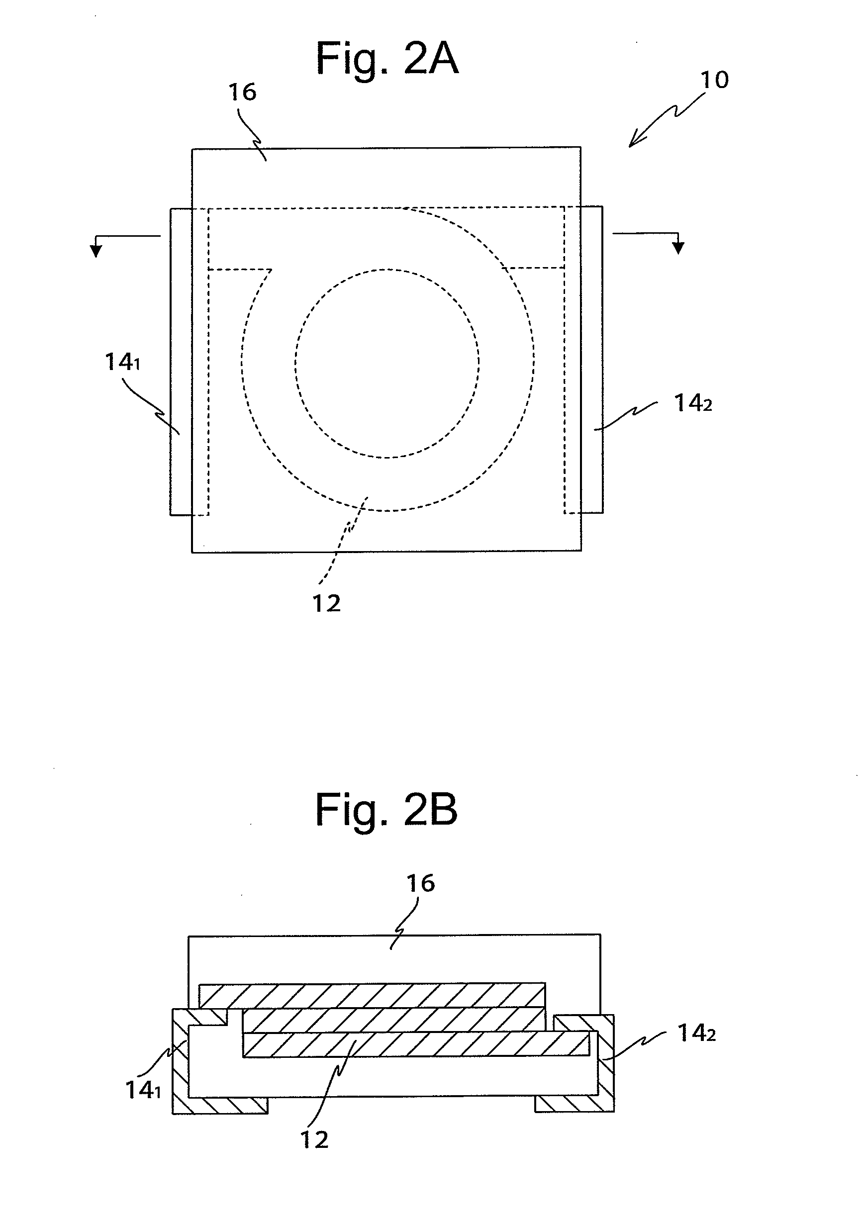
Image

Examples
example 1
Study of Mn Content
(1) Production of Magnetic Material
[0046]Shape variation of the particle based on the content of Mn under the certain amount of Si and Cr was observed with a scanning electron microscope, and the ratio of powder particles of which the major / minor axis ratio is equal to or greater than 2 and the average particle size were calculated. The content of Mn was set to those shown in Table 2 and particles were produced using a widely-known water atomizing method. The produced powder with an average particle size equal to or less than 10 μm was used.
TABLE 2Mn ContentRatio of Particles with Major / minorAverage Particle(wt %)axis Ratio of 2 or more (%)Size (μm)0.265.50.2555.40.43.95.70.53.35.50.62.75.70.825.511.35.61.115.730.185.53.20.155.5
[0047]As shown in Table 2, as the content of Mn increases, it was observed that the ratio of particles of which the major / minor axis ratio is not less than 2 decreases and the average particle size is not changed drastically.
[0048]The follo...
example 2
Study of Content of Si
[0070]The dust cores having the compositions shown in Table 4 were produced and their properties were evaluated by using the relative permeability and the core loss. The measurement conditions of the core loss were the same as those of Example 1. The results are shown in Table 4.
TABLE 4RelativePerme-Alloy abilityPcv*2CompositionEvalu-Evalu-MnSiCrFeμration*1(w / cm3)ation*3Com- 0.80.84Balance26.4A5.5Cparative Example 3Exam- 90.814Balance26.4A5Aples100.834Balance26A4.4A110.844Balance25A4.2A120.854Balance23.9A4A130.874Balance20A4.8ACom-0.87.24Balance18C5.1CparativeExample 4*1The relative permeability greater than 19.0 was evaluated as A and the relative permeability less than 19.0 was evaluated as C.*2The measuring conditions of Pcv were set to Bm-50 mT and f = 500 kHz.*3The core loss equal to or less than 5.0 (w / cm3) was evaluated as A and the core loss greater than 5.0 (w / cm3) was evaluated as C.
[0071]Both of the dust core of Comparative Example 3 of which Si cont...
example 3
Study of Content of Cr
[0073]The dust cores having the compositions shown in Table 5 were produced and their properties were evaluated by using the relative permeability and the rust generation. The dust cores used to evaluate the rust generation in the example were subjected to an antirust treatment. After that, the rust generation was observed and evaluated with the naked eye. An inorganic antirust aqueous solution containing boron oxide and sodium oxide was used in the antirust treatment.
TABLE 5RelativePerme-Corro-ability*1sion*2Alloy CompositionEvalu-EvaluMnSiCrFeμrationationCom- 0.80.81.8Rest26.5ACparativeExample 5Examples 140.812Rest26.5AB150.833Rest26.1AA160.844Rest25AA170.855Rest23.8AA180.878Rest20.5AACom-0.87.28.2Rest18.3CAparativeExample 6*1The relative permeability greater than 19.0 was evaluated as A and the relative permeability less than 19.0 was evaluated as C.*2No rust was evaluated as A, the rust-generated area less than 5% was evaluated as B, and the rust-generated ...
PUM
| Property | Measurement | Unit |
|---|---|---|
| insulation resistivity | aaaaa | aaaaa |
| dielectric breakdown electric field | aaaaa | aaaaa |
| frequency | aaaaa | aaaaa |
Abstract
Description
Claims
Application Information