

Dielectric ceramic composition and electronic device
a technology of ceramic composition and electronic device, which is applied in the direction of fixed capacitors, basic electric elements, electrical apparatus, etc., can solve the problems of reduced effective capacitance under used environment, rapid reduction of specific permittivity, and different problems affecting the ferroelectricity of ceramic composition, etc., and achieve good insulation resistance and good characteristics
- Summary
- Abstract
- Description
- Claims
- Application Information
AI Technical Summary
Benefits of technology
Problems solved by technology
Method used
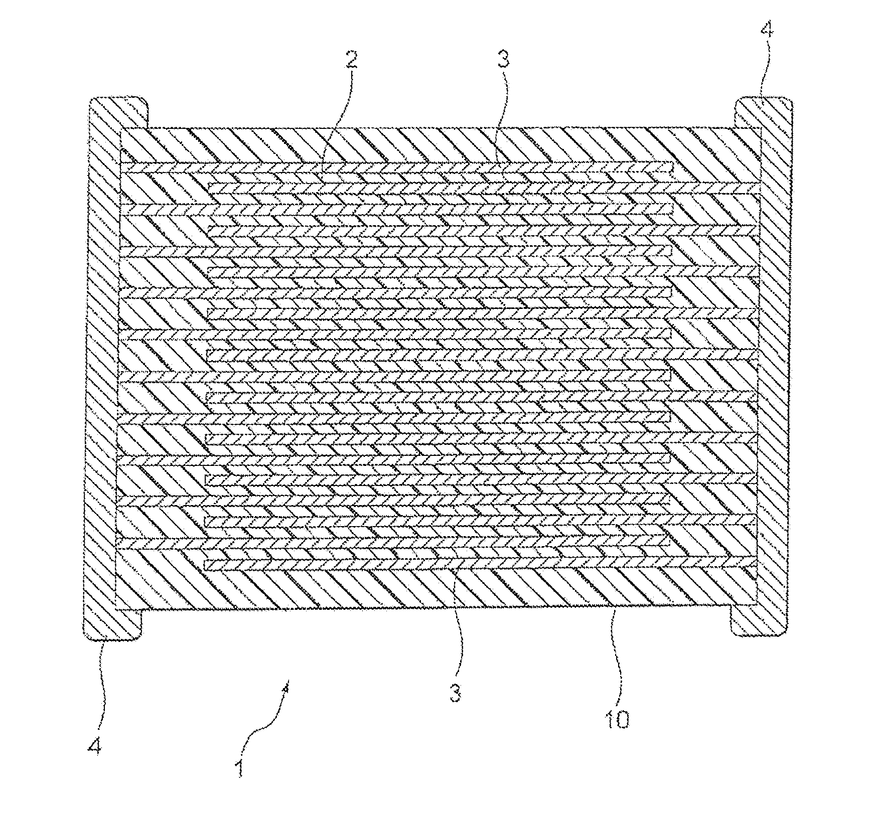
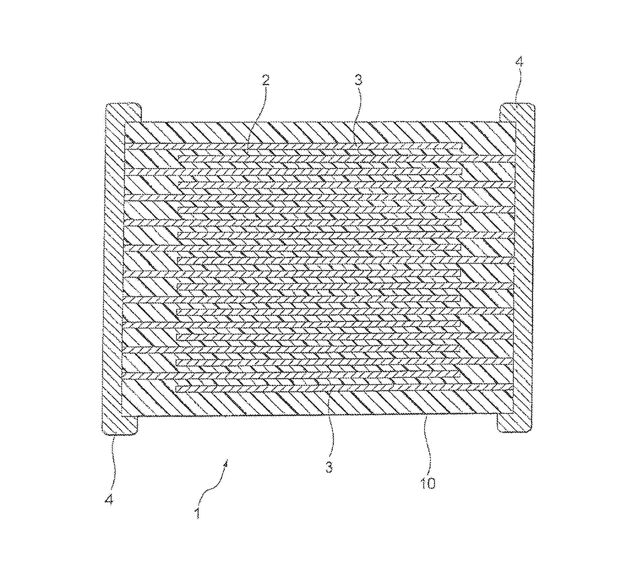
Image

Examples
example 1
[0060]At first, a compound powder shown by a general formula {A1−x(RE)2x / 3}y-B2O5+y was prepared, and this was determined as dielectric raw materials. In the general formula, “A” element is Ba, “RE” element is La, “B” element is Nb, “x” is 0.40 and “y” is the values shown in Table 1.
[0061]Next, ion-exchange water and polyvinyl alcohol were poured in a container, mixed for 2 hours at 85° C., and then polyvinyl alcohol aqueous solution was obtained. Concentration of the aqueous solution was made to 6 wt % by regulating an amount of ion-exchange water.
[0062]20 wt % of polyvinyl alcohol aqueous solution with respect to 100 wt % of the prepared dielectric raw materials was added, mixed and granulated in a mortar, and then granulated powder was obtained. The obtained granulated powder was poured into a mold of Φ11.1 mm, press formed under a pressure of 10 kg / cm2, and then a disk-shaped green compact was obtained.
[0063]Next, the obtained green compact was fired in air and a disk-shaped sin...
example 2
[0079]Samples of ceramic capacitor were manufactured in the same way as sample 2 of Example 1, except using a mixture of a powder of the compound used in example 1 and an oxide powder shown in Table 2 as dielectric raw materials. And then the same evaluation as example 1 was performed. Results are shown in Table 2.
[0080]Note that oxide powder content of each samples 20 to 24 was set to be 1.0 mole in terms of element with respect to 100 moles of a compound. Further, a total content of V oxide and Mn oxide in sample 25 was set to be 1.0 mole in terms of element with respect to 100 moles of the compound.
[0081]
TABLE 2characteristics of a sintered bodyFiringContractionInsulation(Ba1−xLa2x / 3)yNb2O5+yOxideTemperatureRatioSpecificResistivitySamplesxyKind[° C.][%]Permittivity[Ω· m]20.401.002none130017.53901.2E+12200.401.002V127518.14111.3E+12210.401.002Fe130018.03741.3E+12220.401.002Mo130018.04131.3E+12230.401.002W130018.33991.2E+12240.401.002Mn130018.04051.2E+12250.401.002V, Mn127518.64021...
example 3
[0083]Samples of ceramic capacitor were manufactured in the same way as sample 20 of Example 2, except V oxide content is as shown in Table 3. Results are shown in Table 3. Note that “y” values of samples 26 to 28 are shown in table 3.
[0084]
TABLE 3characteristics of a sintered bodyOxideContractionInsulation(Ba1−xLa2x / 3)yNb2O5+yContentRatioSpecificResistivityDC-BiasSamplesxyKind[mol][%]Permittivity[Ω· m](20 V / μm)20.401.002—17.53901.20E+12−2%20a0.401.002V0.0117.53951.22E+12−2%20b0.401.002V0.0517.64021.25E+12−2%20c0.401.002V0.518.04051.28E+12−2%200.401.002V1.018.14111.30E+12−2%20d0.401.002V2.518.33901.35E+12−2%20e0.401.002V5.018.43701.28E+12−2%20f0.401.002V7.018.52901.25E+12−2%260.401.010V1.017.4360 1.2E+12−2%270.401.300V1.016.5170 1.2E+12−1%280.401.500V1.015.337 1.4E+12 0%“mE+n” indicates “m × 10n”
[0085]From table 3, it was confirmed that V oxide content is preferably within a range of 0.05 to 5 mol %. Further, good values could be obtained even when “y” value changed. Note that conte...
PUM
| Property | Measurement | Unit |
|---|---|---|
| mole ratio | aaaaa | aaaaa |
| holding temperature | aaaaa | aaaaa |
| holding temperature | aaaaa | aaaaa |
Abstract
Description
Claims
Application Information