
Fiber optic sensor for detecting multiple parameters in a harsh environment

a technology of fiber optic sensors and bragg grating, which is applied in the field of fiber optic sensors, can solve the problems of affecting the thermal stability of such sensors, affecting the performance of such sensors,

Active Publication Date: 2011-07-14
GENERAL ELECTRIC CO
View PDF19 Cites 27 Cited by
  • Summary
  • Abstract
  • Description
  • Claims
  • Application Information

AI Technical Summary

Problems solved by technology

Such dopants lead to formation of intra-band impurity energy levels in a silicon dioxide band gap.
Furthermore, the dopants distributed in these impurity bands can be thermally excited to a conduction band and consequently induce thermal variation of the conductivity thereby causing degradation of the refractive index modulation of the fiber grating structure.
Therefore, thermal stability of such sensors is limited by the operational conditions in which they may be employed.
Current fiber Bragg grating sensors are typically limited to be operated to temperatures less than about 120° C. because of temperature dependent dopant diffusion induced grating fading.
A thermal post-treatment process is typically used for stabilising the fiber grating's refractive index modulation amplitude, but such fiber Bragg grating-based sensors still have low reliability while operating above the annealing temperature.
Furthermore, as with the thermal effect, any high-energy radiations, gamma-ray and neutrons, in an environment like nuclear reactor also can prompt dopant diffusion and formation of color centers, and other defects that can lead to degradation of the fiber grating structure and the refractive index modulation.
However, such sensing devices are also limited to low-temperature environmental applications, and suffer from electromagnetic interference and radiation degradation issues.

Method used


Image

  • Fiber optic sensor for detecting multiple parameters in a harsh environment
  • Fiber optic sensor for detecting multiple parameters in a harsh environment
  • Fiber optic sensor for detecting multiple parameters in a harsh environment

Examples


Embodiment Construction

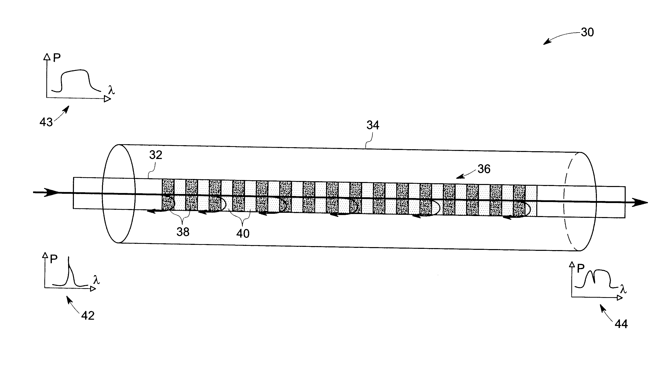
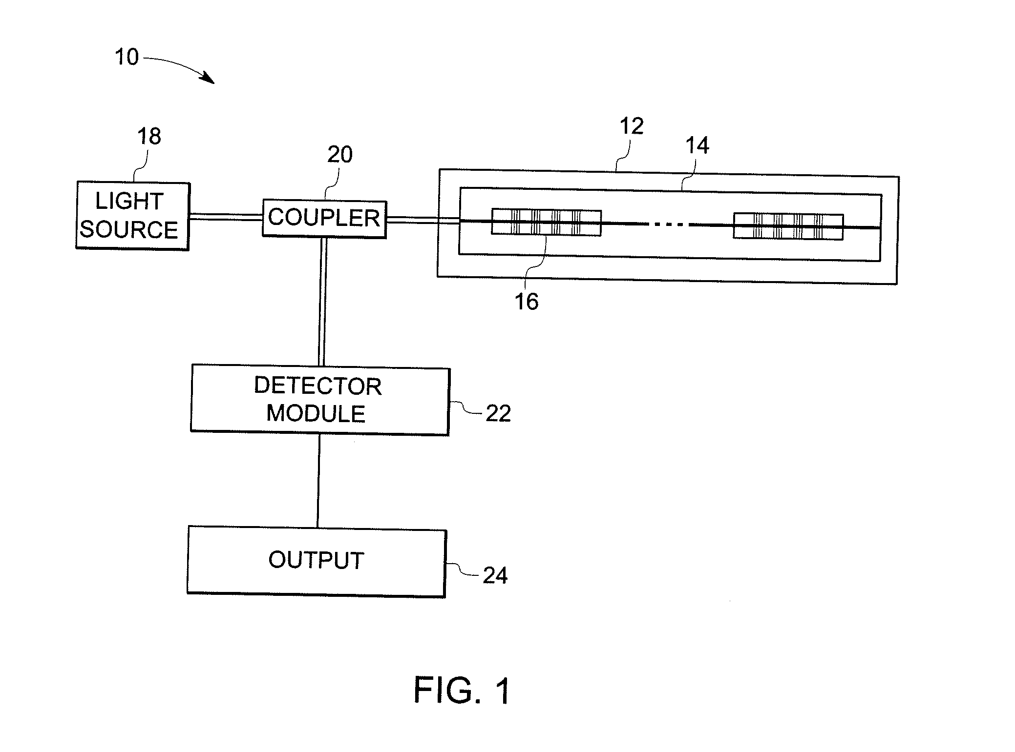
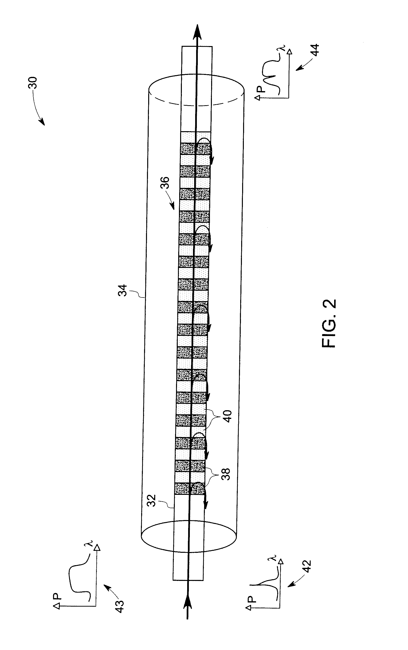
[0037]Referring now to drawings, FIG. 1 illustrates an exemplary fiber optic sensing system 10 for detecting multiple parameters in a harsh environment and / or for an object 12. Although the present discussion focuses on sensing devices and systems, the embodiments are not limited to the sensing field, but are also applicable to other modalities, such as, optical filters, data transmission, and telecommunications, among others. Accordingly, the appended claims should not be limited to or by the exemplary embodiments of the following discussion. The fiber optic sensing system 10 includes a plurality of fiber optic sensors such as represented by reference numeral 14 that, in turn, includes a grated cable 16. As illustrated, the cable 16 is disposed within the element 12, causing changes in the element 12 to translate to the cable 16. The grated cable 16 includes a core that has a plurality of grating elements having a periodic or a quasiperiodic modulated grating structure, which is de...


PUM


Abstract

A fiber optic sensor is provided. The fiber optic sensor includes a fiber core having a plurality of grating elements wherein, the grating elements comprise a periodic or a quasiperiodic modulated microcrystalline and silicon dioxide tetrahedral structure and a cladding disposed about the fiber core.

Description

CROSS REFERENCE TO RELATED APPLICATIONS[0001]This application is a Continuation in Part of U.S. patent application Ser. No. 11 / 689,850, filed 22 Mar. 2007, which is herein incorporated by reference.BACKGROUND[0002]The invention relates generally to fiber optic sensors, and more particularly to a fiber optic Bragg grating sensor for detecting multiple parameters in a harsh environment.[0003]Various fiber optic sensing devices are known and are in use for physical and chemical detection and measurement. As one example, fiber Bragg grating sensors are employed to measure parameters such as strain, vibrations, pressure, flow rate and temperature in components such as exhaust systems, nuclear reactors, combustors and compressors. Conventional fiber Bragg grating sensors employed for dynamic strain and temperature measurements include a grating structure inscribed on to a photosensitive single-mode fiber core. Typically, the fiber core is doped with Germanium oxides or co-doped with boron...

Claims


Application Information

Patent Timeline
IPC IPC(8): G02B6/02G02B1/12
CPCG01D5/35303G01D5/35316G02B6/021G02B6/02209G02B6/02147G02B6/02185G02B6/02138G01D5/35341
Inventor XIA, HUABALASUBRAMANIAM, MAHADEVANJIANG, JIELUO, HUAGENGAL-KHALIDY, ABDUL RAHMAN ABDALLAHYOUNG, CLAYTON MINGMCCARTHY, KEVIN THOMAS
Owner GENERAL ELECTRIC CO
Learn More