Examination of biological tissue using non-contact optical probes

a non-contact, optical probe technology, applied in the direction of medical science, diagnostics, diagnostics using light, etc., can solve the problems of reducing the effective numerical aperture, reducing the light collection efficiency, etc., to prevent the detection of “noise” photons, eliminate “noise” photons, and reduce light collection efficiency

Inactive Publication Date: 2011-07-14
CHANCE BRITTON
View PDF99 Cites 15 Cited by
  • Summary
  • Abstract
  • Description
  • Claims
  • Application Information

AI Technical Summary

Benefits of technology

[0012]According to one aspect, an optical system for examination of biological tissue includes a light source, a light detector, optics and electronics. The light source generates a light beam to be transmitted to the biological tissue spaced apart from the source. The light detector is located away (i.e., in a non-contact position) from the examined biological tissue and is constructed to detect light that has migrated in the examined biological tissue. The electronics controls the light source and the light detector, and a system separates the reflected photons (e.g., directly reflected or scattered from the surface or superficial photons) from the photons that have migrated in the examined biological tissue. The system prevents detection of the “noise” photons by the light detector or, after detection, eliminates the “noise” photons in the detected optical data used for tissue examination.
[0013]The optical system including its electronics may comprise a time-resolved spectroscopic (TRS) system, a phase modulation system (PMS), a phased array system, or a continuous wave (CW) system. In each case, the detector is located away from the examined tissue and there is no optical fiber in contact with the tissue surface. Conventionally, this reduces the light collection efficiency (reduces the effective numerical aperture), which in prior art was considered as a barrier to an effective spectrophotometric system. Thus, the present invention “discarded” the conventional concept.
[0014]According to another aspect, an optical system for examination of brain tissue of a subject undergoing a security check includes a light source, a light detector, optics and electronics. The light source generates a light beam to be transmitted to the head of the subject spaced apart from the source. The light detector is located away from the head and is constructed to detect light that has migrated in the biological tissue being examined. The electronics controls the light source and the light detector, and a system separates the reflected photons from the photons that have migrated in the examined biological tissue to prevent detection of the reflected photons by the light detector or eliminate after detection the reflected photons in the detected optical data used for tissue examination.
[0019]Furthermore, the described systems can be used as “deceit measure detectors” that provide strong signal at the signature voxel when the subject is lying and provide weak signal at the signature voxel when the subject is telling the truth.

Problems solved by technology

Conventionally, this reduces the light collection efficiency (reduces the effective numerical aperture), which in prior art was considered as a barrier to an effective spectrophotometric system.

Method used


Image

  • Examination of biological tissue using non-contact optical probes
  • Examination of biological tissue using non-contact optical probes
  • Examination of biological tissue using non-contact optical probes

Examples


Embodiment Construction

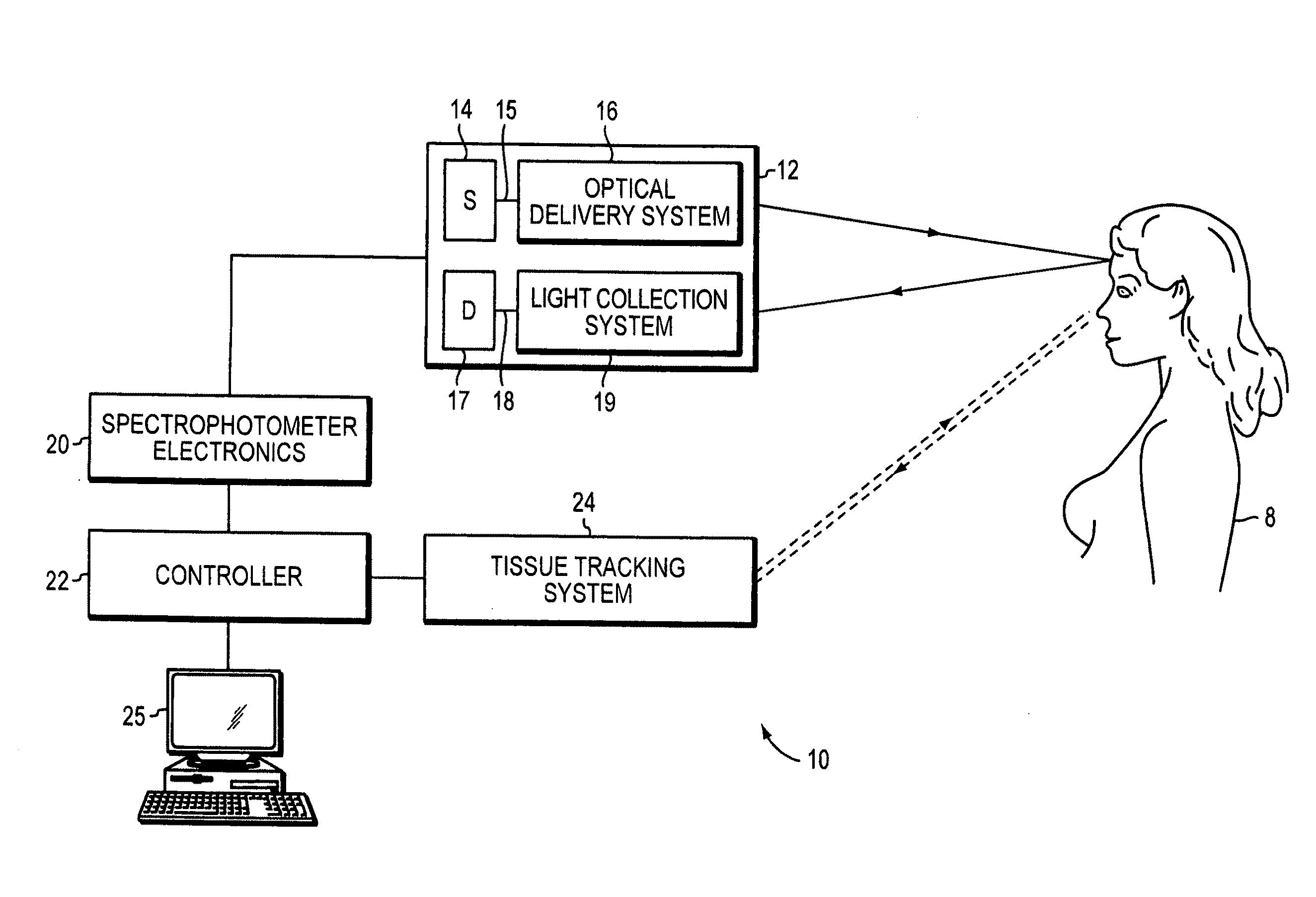
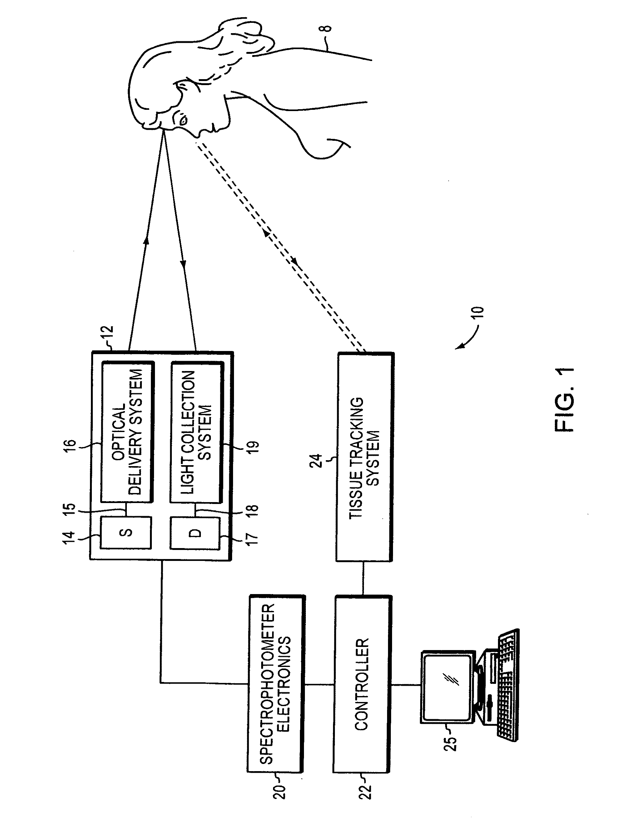
[0035]FIG. 1 shows schematically a non-contact optical system 10 including a non-contact optical probe 12, spectrophotometer electronics 20, a system controller 22, a tissue tracking system 24 and a computer 25. Spectrophotometer electronics 20 controls optical probe 12, including light emission from a light source 14, light delivery or scanning by an optical delivery system 16, light collection and receiving by a light collection system 19 and the corresponding detection by a light detector 17. Light source 14 emits a light beam of a selected wavelength focused and / or scanned over the examined tissue surface by delivery system 16. Light detector 17 receives light from a light collection system 19, which collects light emanating from the tissue surface. A controller 22 controls the entire operation of the spectrophotometer (including electronics 20 and optical probe 12) and controls operation of a tissue tracking system 24.

[0036]Tissue tracking system 24 is optional and operates tog...


PUM


Abstract

An optical system for examination of biological tissue includes a light source, a light detector, optics and electronics. The light source generates a light beam to be transmitted to the biological tissue spaced apart from the source. The light detector is located away (i.e., in a non-contact position) from the examined biological tissue and is constructed to detect light that has migrated in the examined biological tissue. The electronics controls the light source and the light detector, and a system separates the reflected photons (e.g., directly reflected or scattered from the surface or superficial photons, i.e., “noise” photons) from the photons that have migrated in the examined biological tissue. This system prevents detection of the “noise” photons by the light detector or, after detection, eliminates the “noise” photons in the detected optical data used for tissue examination.

Description

[0001]This application is a continuation of U.S. application Ser. No. 10 / 752,440, filed on Jan. 5, 2004, now U.S. Pat. No. 7,840,257, entitled “Examination of Biological Tissue using Non-Contact Optical Probes,” which claims priority from U.S. Provisional Application 60 / 438,229, filed on Jan. 4, 2003, which is incorporated by reference. The U.S. application Ser. No. 10 / 752,440 is also a continuation-in part of U.S. application Ser. No. 10 / 618,579, filed on Jul. 10, 2003, entitled “Examination and Imaging of Brain Cognitive Functions,” which is incorporated by reference.[0002]The present invention relates to in vivo non-invasive examination or imaging of biological tissue using non-contact spectroscopic systems.BACKGROUND OF THE INVENTION[0003]X-ray or γ-ray radiation, optical radiation, ultrasound waves and magnetic field have been used to examine and image biological tissue. X-rays or γ-rays propagate in the tissue on straight, ballistic lines, that is, their scattering is negligib...

Claims


Application Information

Patent Timeline
Patent Type & Authority Applications(United States)
IPC IPC(8): A61B5/00
CPCA61B5/6834A61B5/0059A61B5/0035A61B5/0042
Inventor CHANCE, BRITTON
Owner CHANCE BRITTON
Why Eureka
Try Eureka