Internal combustion engine system control device

a control device and combustion engine technology, applied in the direction of electrical control, process and machine control, etc., can solve the problems of more difficult to accurately estimate the amount of in-cylinder air than in the case of natural aspiration, the difficulty of accurately estimating the exhaust parameters based on measurements using sensors and calculations, and the difficulty of accurately estimating the supercharging pressure and in-cylinder air amount in the configuration of the related art, so as to achieve more accurate control and estimate the effect of accuracy

Inactive Publication Date: 2011-07-14
TOYOTA JIDOSHA KK
View PDF5 Cites 10 Cited by
  • Summary
  • Abstract
  • Description
  • Claims
  • Application Information

AI Technical Summary

Benefits of technology

[0011]The invention provides an internal combustion engine system control device that enables the in-cylinder air amount in an internal combustion engine system provided with a supercharger to be estimated more accurately. In addition, the invention provides an internal combustion engine system control device that enables an internal combustion engine system provided with a supercharger to be controlled more accurately using an inexpensive device configuration.

Problems solved by technology

Accordingly, in the case of an internal combustion engine system provided with a supercharger, it is more difficult to accurately estimate in-cylinder air amount than in the case of natural aspiration.
Accordingly, it is difficult to accurately estimate exhaust parameters based on measurements using sensors and calculations.
Consequently, it is difficult to accurately estimate supercharging pressure and in-cylinder air amount in a configuration of the related art using characteristics of the exhaust system (such as in the configuration disclosed in JP-A-2006-22763).
In addition, providing sensors in the exhaust system for acquiring exhaust temperature and turbine rotating speed (which is equal to compressor rotating speed) results in increased costs.
Thus, in a device of the related art that uses measurement and estimation of exhaust parameters (such as that disclosed in JP-A-2006-22763), it is difficult to accurately control this type of internal combustion engine system with an inexpensive device configuration.

Method used


Image

  • Internal combustion engine system control device
  • Internal combustion engine system control device
  • Internal combustion engine system control device

Examples


first embodiment

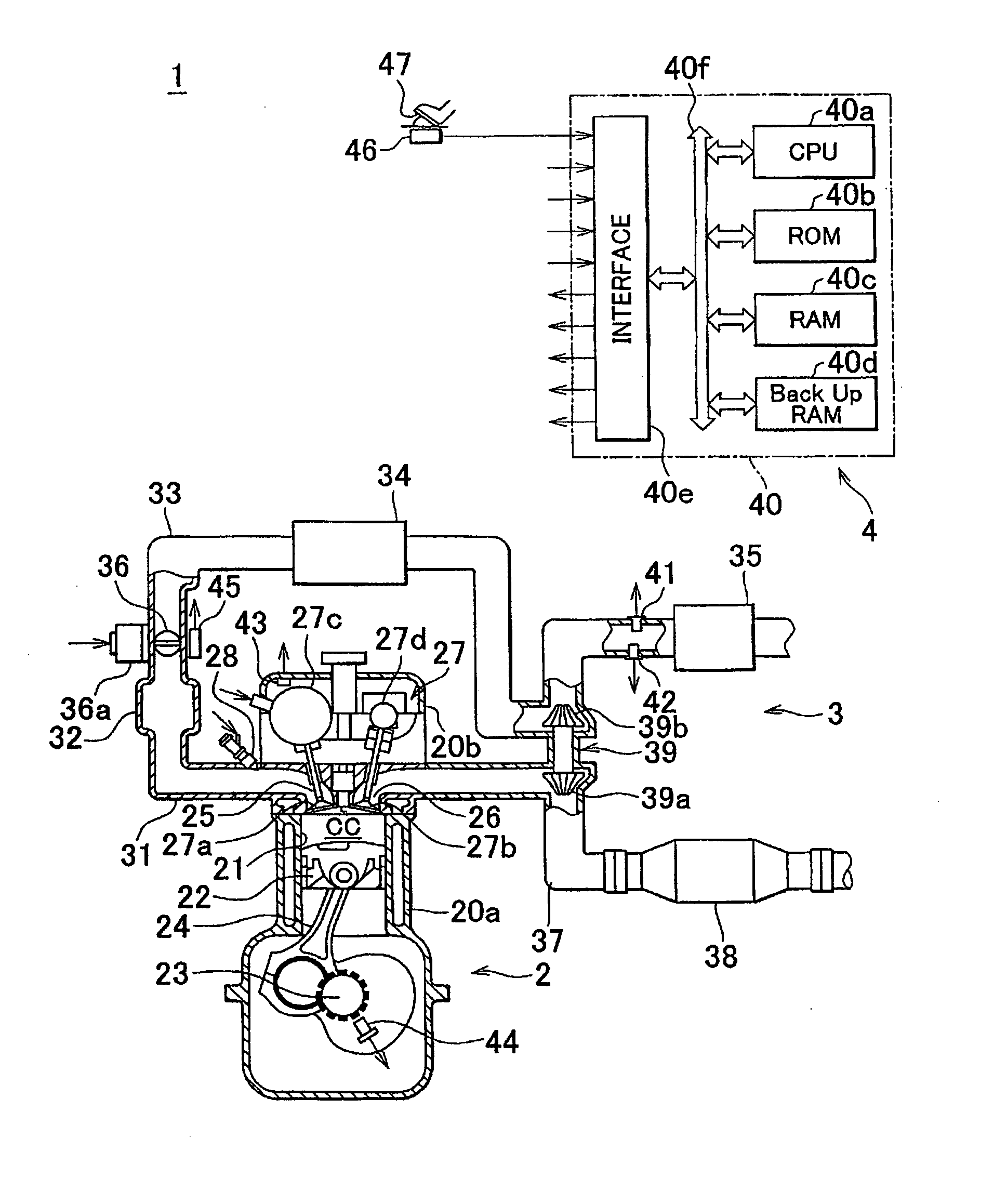
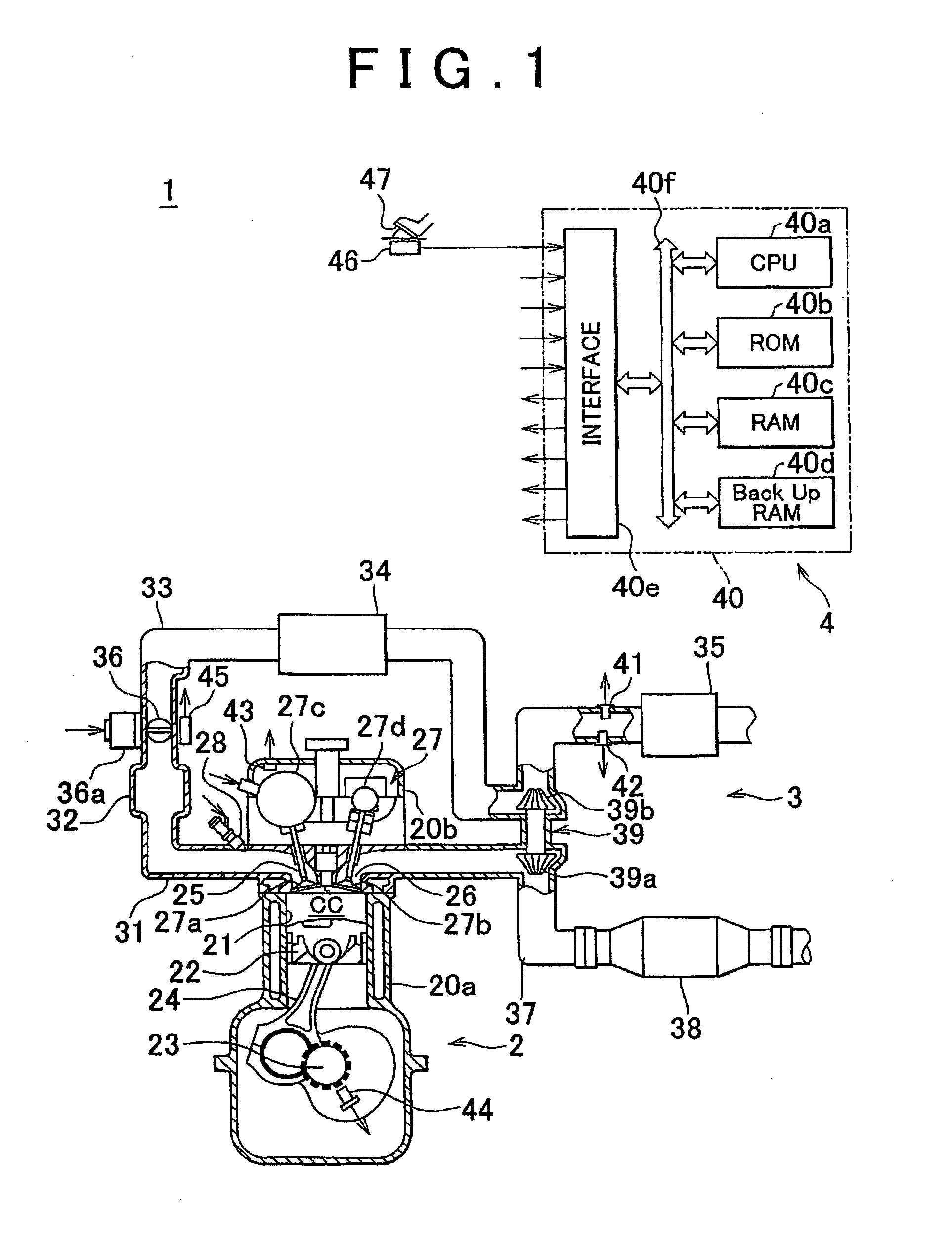
[0133]FIG. 1 is a drawing schematically showing the overall configuration of an internal combustion engine system 1 to which the invention is applied. This internal combustion engine system 1 is provided with an inline multi-cylinder internal combustion engine 2, an intake / exhaust system 3 and a control device 4 (in FIG. 1, a cross-sectional view of the internal combustion engine 2 is shown using a plane that is perpendicular to the direction of the arrangement of cylinders). The following provides a more detailed explanation of the configuration of each portion of the internal combustion engine system 1.

[0134] An explanation is first provided of the configuration of the internal combustion engine 2.

[0135]A cylinder block 20a, which includes a lower case, an oil pan and the like, is a member that composes the main unit portion (engine block) of the internal combustion engine 2 together with a cylinder head 20b. The cylinder head 20b is fixed to the upper end of the cylinder block 20...

second embodiment

[0313] Furthermore, in the second embodiment as described above, the applicant has merely illustrated a typical embodiment of the invention considered to be the best mode for carrying out the invention at the time of filing. Accordingly, the invention is naturally not limited in any way to the embodiment described above. Thus, it goes without saying that various modifications with respect to the embodiment described above can be carried out within a range that does not deviate from the essential portions of the invention.

[0314]The following provides a description of several examples of typical variations. It goes without saying that the variations are not limited to those listed below. In addition, all or a portion of a plurality of variations can be suitably mutually combined within a range that is not technically conflicting. The invention (and particularly that represented in terms of action or function among the constituents that compose the means for solving the problems of the...

third embodiment

[0323]The following provides an explanation of an internal combustion engine to which the control device of the invention is applied with reference to the drawings. FIG. 22 shows a spark ignition-type internal combustion engine to which the control device of the invention is applied. Furthermore, the internal combustion engine shown in FIG. 22 is a multi-cylinder internal combustion engine provided with multiple combustion chambers, or in other words, multiple cylinders. The configuration of only one specific cylinder is shown in FIG. 22, and the remaining cylinders are provided with a configuration similar thereto.

[0324]The internal combustion engine 110 shown in FIG. 22 is provided with a cylinder block unit 120 that includes a cylinder block, a cylinder block lower case and an oil pan and the like, a cylinder head unit 130 fixed on the cylinder block unit 120, an intake system 140 for supplying a fuel-air mixture composed of fuel and air to the cylinder block unit 120, and an exh...


PUM


Abstract

A device with models constructed based on thermodynamics laws and fluid dynamics laws including the energy conservation law, momentum conservation law and mass conservation law. Compressor outflow flow rate calculation section calculates the flow rate of air that flows out of a compressor based on a relationship between an in-cylinder intake air flow rate during steady-state operation in an internal combustion engine system and supercharging pressure, which is pressure of air compressed by the compressor, and a value of the in-cylinder intake air flow rate calculated by in-cylinder intake air flow rate calculation section.

Description

BACKGROUND OF THE INVENTION[0001]1. Field of the Invention[0002]The invention relates to an internal combustion engine system control device that controls an internal combustion engine system provided with a supercharger having a compressor that compresses air inside an intake passage.[0003]2. Description of the Related Art[0004]In order to make the air-fuel ratio of a fuel-air mixture supplied to the cylinders of a fuel combustion engine equal to a target air-fuel ratio, the amount of air introduced into the cylinders (to be referred to as in-cylinder air amount) must be estimated accurately.[0005]However, a supercharger may be installed in the intake system of an internal combustion engine for the purpose of, for example, improving maximum output of the internal combustion engine. In this case, air inside the intake passage is compressed by the supercharger. Consequently, the pressure and temperature of air upstream from the throttle valve vary suddenly in comparison with atmosphe...

Claims


Application Information

Patent Timeline
Patent Type & Authority Applications(United States)
IPC IPC(8): F02D41/00
CPCF02D41/0007F02D41/18Y02T10/144F02D2200/0402F02D2200/0411F02D2041/1433Y02T10/12
Inventor EIRAKU, AKIRAKATSUMATA, MACHIKO
Owner TOYOTA JIDOSHA KK
Why Eureka
Try Eureka