Massively Distributed Processing System Architecture, Scheduling, Unique Device Identification and Associated Methods

a distributed processing and system architecture technology, applied in data processing applications, multiple digital computer combinations, computing, etc., can solve the problems of large processing power needed to analyze these data recordings, inefficient architecture, and often incurred costs for departments within the company relating to using processing time, etc., to achieve the effect of enhancing system operations and functionality

Inactive Publication Date: 2011-07-14
HUBBARD EDWARD A +6
View PDF5 Cites 31 Cited by
  • Summary
  • Abstract
  • Description
  • Claims
  • Application Information

AI Technical Summary

Benefits of technology

[0012]The present invention provides a massively distributed processing system and associated methods that utilize an advantageous processing architecture for a multitude of widely distributed devices to process distributed workloads for a plurality distributed processing projects. To provide the infrastructure processing power for the distributed processing system, a modular client agent program, including a system component with a core agent module and a separate project component with at least one task module, is configured to operate on the distributed devices and to process a variety of project workloads. For each different distributed project, different project components or task modules may be provided by a server system to the distributed devices to run on the core agent module or

Problems solved by technology

Using small segments of mainframe processing time, departments within the company would often incur costs associated with using the processing time, which in turn was billed back to each department from the central information technology (IT) organization for the company.
The processing power needed to analyze these data recordings was very large.
These

Method used


Image

  • Massively Distributed Processing System Architecture, Scheduling, Unique Device Identification and Associated Methods
  • Massively Distributed Processing System Architecture, Scheduling, Unique Device Identification and Associated Methods
  • Massively Distributed Processing System Architecture, Scheduling, Unique Device Identification and Associated Methods

Examples


embodiment 1600

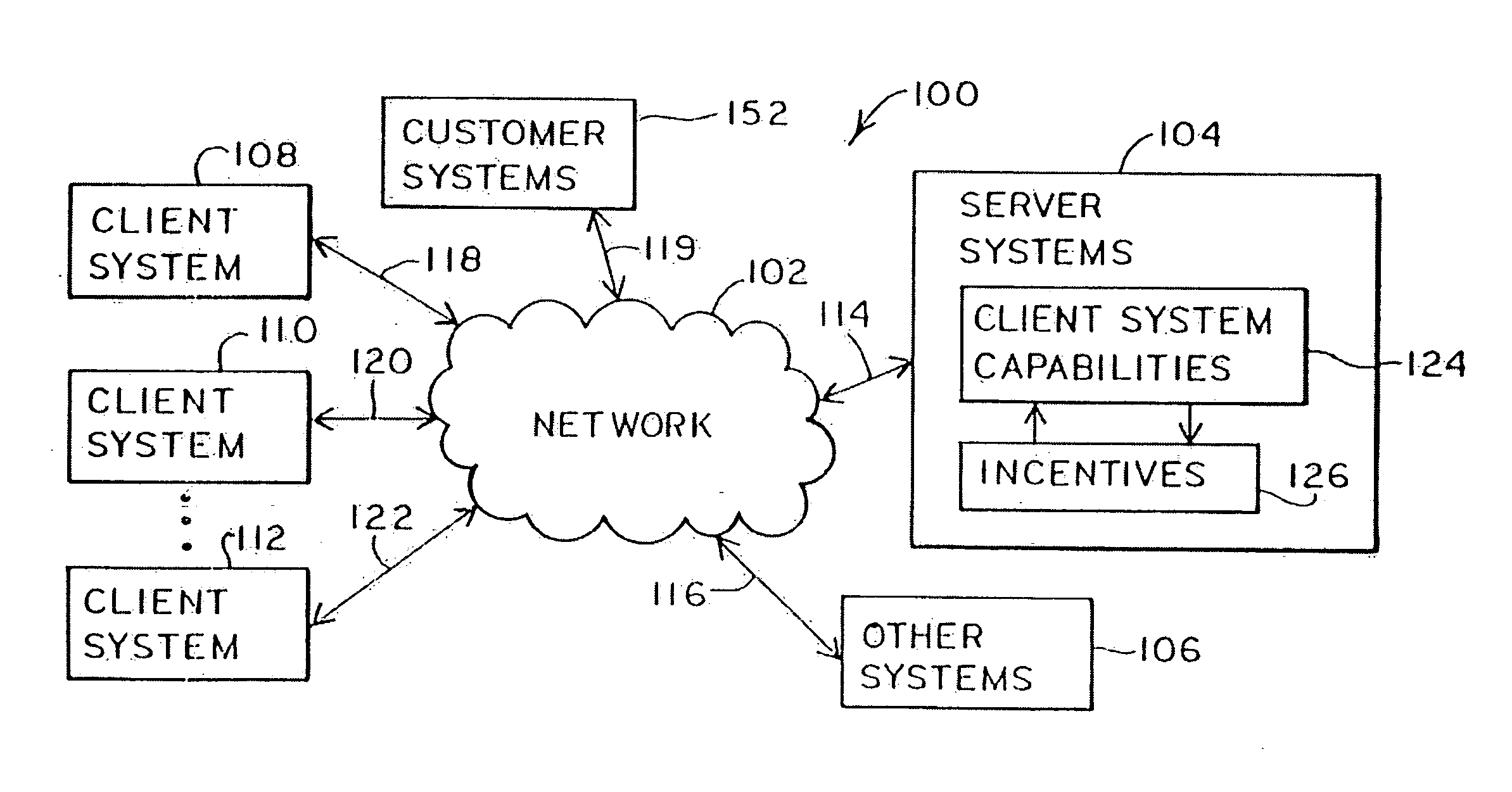
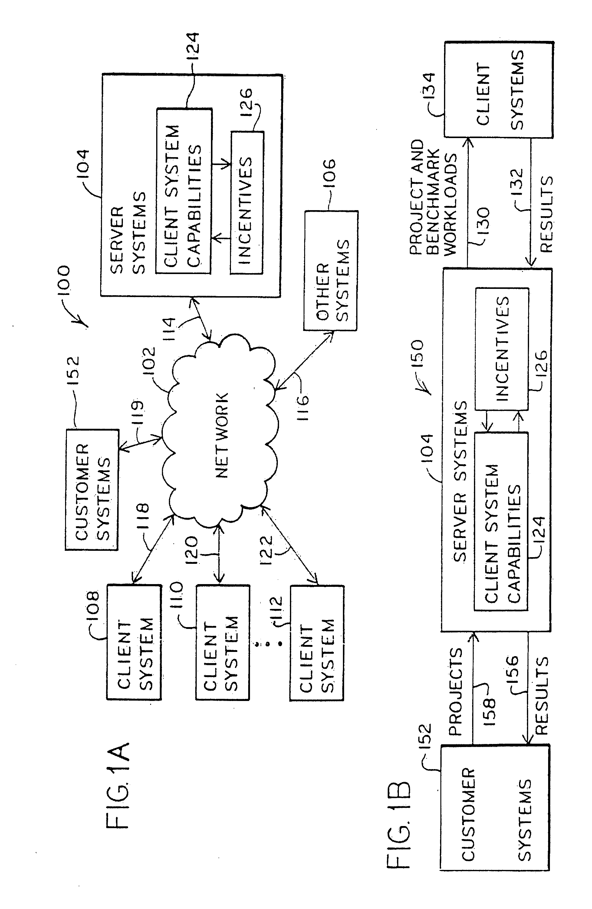
[0165]Referring to FIG. 16, an embodiment 1600 of a distributed processing system is depicted. Server systems 104 include a security subsystem 354 through which communications to and from the server systems 104 may be made secure. Client systems 108A, 108B . . . 108C and client systems 108D, 108E . . . 108F represent any number of client systems that may communicate with server systems 104 or with each other. Each of the client systems 108A, 108B, 108C, 108D, 108E and 108F include a security subsystem 272A, 272B, 272C, 272D, 272E and 272F, respectively. The electronic information 1602 represents information that the server systems 104 is to communicate to client systems 108A, 108B, 108C, 108D, 108E and 108F in a secure manner, so that no unintended or intercepting recipient may understand or tamper with the electronic information 1602, and so that no third party may insert non-authorized information into the distributed processing system 1600. Although not shown, it is understood th...

embodiment 1800

[0177]FIG. 18A is a block diagram of an embodiment 1800 for security procedures implemented by server systems 104. Electronic information 1602 is to be communicated to a client system 108. This electronic information 1602 travels through four different paths that provide security information.

[0178]One path begins with the electronic information 1602 being encrypted with the server private key in block 1802. Then, in block 1830, the encrypted information is sent to client systems. This encrypted information is represented by arrow 1826.

[0179]A second path flows from block 1802 to block 1804 where a hash value is generated for the encrypted electronic information. It is noted that a hash value is a unique value that may be generated for any given electronic file based upon the contents of that file and the algorithm used to calculate the unique value. There are any number of algorithms that may be used to calculate a hash value, as would be understood by one of skill in the art. Proce...

embodiment 1850

[0182]Looking now to FIG. 18B, the corresponding security procedures implemented by a client system 108 are discussed with respect to embodiment 1850. Initially, in block 1854, the client system 108 receives CA certificate 1852 containing the server public key and the server identity. It is again noted that other unique identifiers may be utilized instead of CA certificates, as described above. If a CA certificate is utilized, this CA certificate may be provided from a third-party Certificate Authority (CA) or from the server systems 104 or any other desired source. In block 1856, the client system 108 verifies the accuracy of the CA certificate using the CA's public key. If this verification is not successful, the client system 108 may wait some period of time before retrying. In addition, the time period may be a random period of time. In addition, as discussed with respect to FIGS. 17A and 17B, the client system 108 will login to the server systems 104. If this authentication is ...


PUM


Abstract

A massively distributed processing system and associated methods are described that utilize an advantageous processing architecture for a multitude of widely distributed devices to process distributed workloads for a plurality distributed processing projects. To provide the infrastructure processing power for the distributed processing system, a modular client agent program, including a system component with a core agent module and a separate project component with at least one task module, is configured to operate on the distributed devices and to process a variety of project workloads. For each different distributed project, different project components or task modules may be provided by a server system to the distributed devices to run on the core agent module or system component. In addition, a capabilities database can be used by a server system to schedule workloads based upon the capabilities of the distributed devices. Furthermore, scheduling, device ID, task wrapper and further infrastructure and application development implementations are also provided.

Description

RELATED APPLICATIONS[0001]This application is a continuation-in-part application of the following co-pending applications: application Ser. No. 09 / 539,448 entitled “CAPABILITY-BASED DISTRIBUTED PARALLEL PROCESSING SYSTEM AND ASSOCIATED METHOD,” application Ser. No. 09 / 539,428 entitled “METHOD OF MANAGING DISTRIBUTED WORKLOADS AND ASSOCIATED SYSTEM,” and application Ser. No. 09 / 539,106 entitled “NETWORK SITE TESTING METHOD AND ASSOCIATED SYSTEM,” each of which was filed on Mar. 30, 2000, and each of which is hereby incorporated by reference in its entirety. This application is also a continuation-in-part application of the following co-pending application: application Ser. No. 09 / 603,740 entitled “METHOD OF MANAGING WORKLOADS AND ASSOCIATED DISTRIBUTED PROCESSING SYSTEM,” and application Ser. No. 09 / 602,983 entitled “CUSTOMER SERVICES AND ADVERTISING BASED UPON DEVICE ATTRIBUTES AND ASSOCIATED DISTRIBUTED PROCESSING SYSTEM,” each of which was filed on Jun. 23, 2000, and each of which...

Claims


Application Information

Patent Timeline
IPC IPC(8): G06F15/16
CPCG06Q30/02G06Q10/06
Inventor HUBBARD, EDWARD A.MANDYAM, SRIRAM S.VENKATRAMANI, KRISHNAMURTHYADIGA, ASHOK K.ANDERSON, DAVID P.HEWGILL, GREG D.LAWSON, JEFF A.
Owner HUBBARD EDWARD A
Why Eureka
Try Eureka