
Ceramic filter element and method of manufacture

a ceramic filter element and filter element technology, applied in the field of diesel particle filter, can solve the problems of reducing filtering efficiency, requiring high tooling cost for shaping, and being relatively expensive to manufacture, so as to reduce gas permeability, reduce pressure loss, and thin wall thickness

Active Publication Date: 2011-07-21
MANN HUMMEL GMBH
View PDF14 Cites 8 Cited by
  • Summary
  • Abstract
  • Description
  • Claims
  • Application Information

AI Technical Summary

Benefits of technology

[0009]A further object of the invention is to provide method of manufacturing a ceramic filter, which is simple to carry out and yields filter bodies distinguished by excellent filtering characteristics.
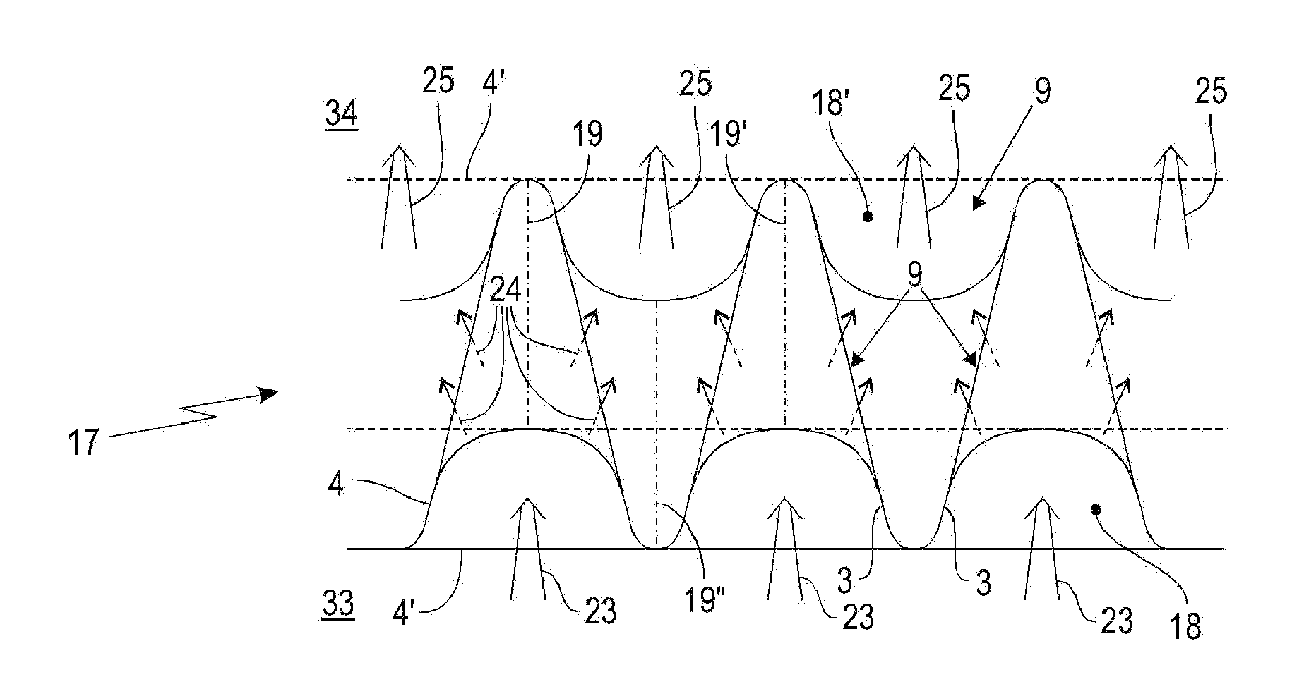
[0038]In one advantageous further embodiment, at least one fiber web has non-impregnated segments to form openings in the filter body. These non-impregnated segments of the filter web burn away during the sintering process. In the absence of ceramic impregnation, openings remain at these points, allowing, for example, an unhindered gas exchange between two adjacent gas channels. This makes it possible to use the flow cross section of all the gas channels for turbulence or for catalytic exhaust gas treatment, for example, e.g., in the inlet or discharge area, either before or after the adjacent plug.

Problems solved by technology

A disadvantage of this ceramic filter element is that it is relatively costly to manufacture.
A further disadvantage is that the inorganic fibers in the finished filter body can reduce the filtering efficiency.
This requires high tooling costs for shaping.
The extrusion process limits the degrees of freedom in the shaping of the filter body, particularly the filter segments and the gas channels.
A flow-optimized design of the diesel particle filter is difficult to achieve.

Method used

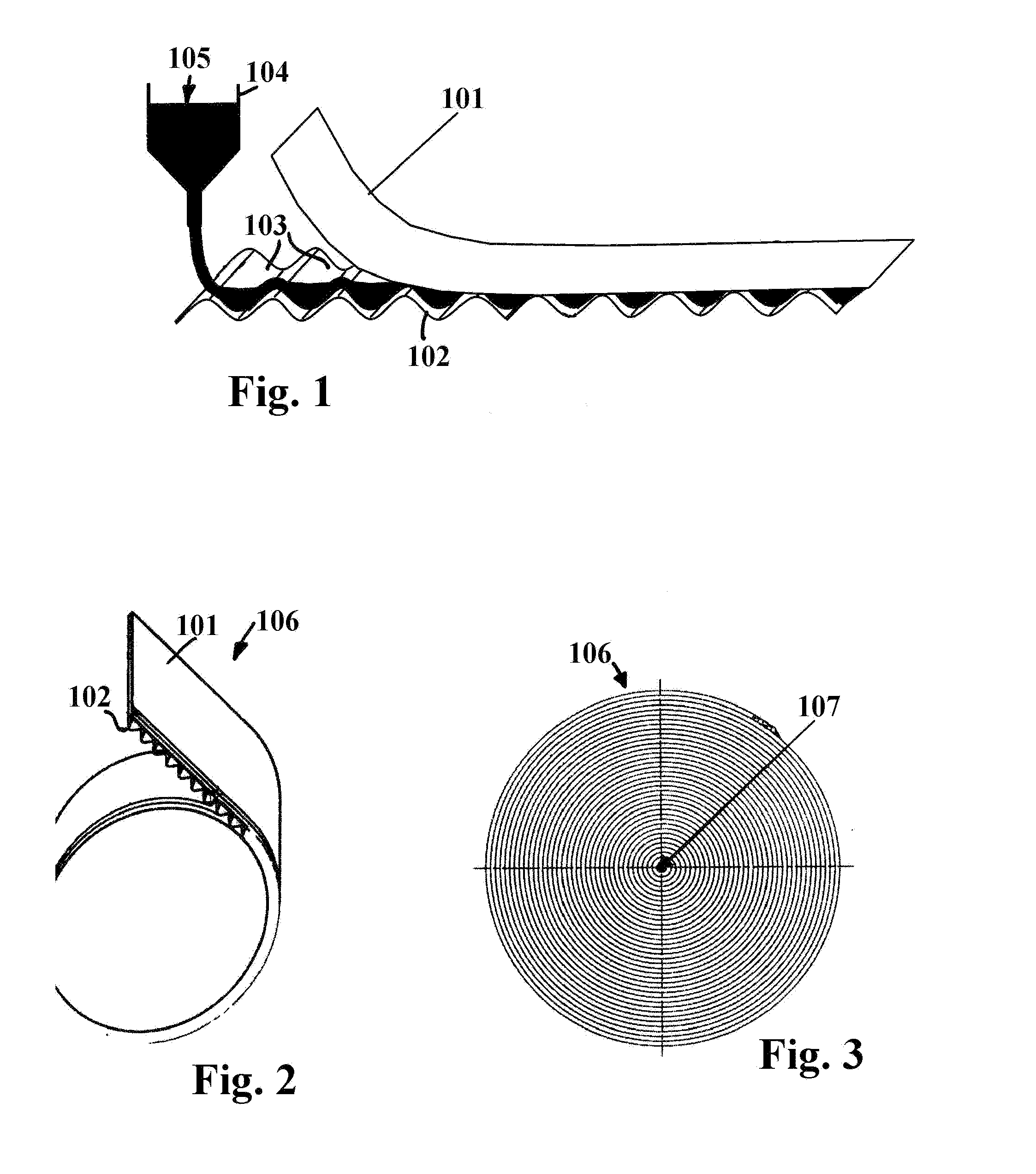

Image

  • Ceramic filter element and method of manufacture
  • Ceramic filter element and method of manufacture
  • Ceramic filter element and method of manufacture

Examples


Embodiment Construction

[0050]Before describing in detail embodiments that are in accordance with the present invention, it should be observed that the embodiments reside primarily in combinations of apparatus components manufacturing methods related to a ceramic filter element which in embodiments is suitable for use as a diesel particulate filter. Accordingly, the apparatus components have been represented where appropriate by conventional symbols in the drawings, showing only those specific details that are pertinent to understanding the embodiments of the present invention so as not to obscure the disclosure with details that will be readily apparent to those of ordinary skill in the art having the benefit of the description herein.

[0051]In this document, relational terms such as first and second, top and bottom, and the like may be used solely to distinguish one entity or action from another entity or action without necessarily requiring or implying any actual such relationship or order between such e...


PUM

PropertyMeasurementUnit
combustibleaaaaaaaaaa
shapeaaaaaaaaaa
geometric shapeaaaaaaaaaa

Abstract

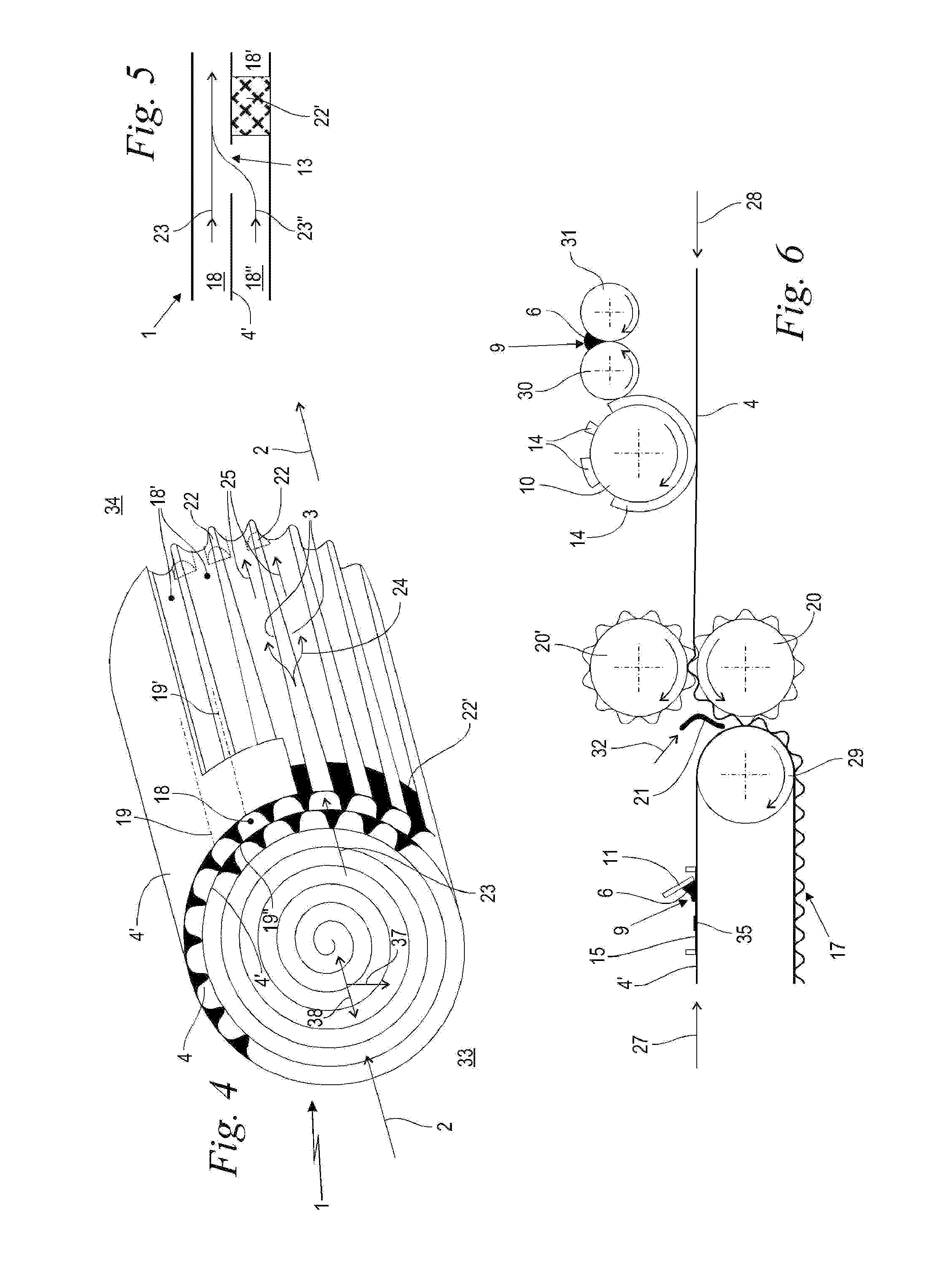
A method of manufacturing a ceramic diesel particle filter (DPF) and a DPF manufactured by the method, the DPF having a ceramic filter body (1) including gas channels (18, 18′) with planar and porous filter segments (3), which are provided for the exhaust gas stream (2) to flow through them transversely to the face of the filter segments (3). The filter body (1) is formed by sintering at least one ceramic-impregnated fiber web (4) in a firing step under heat such that fibers (5) of the fiber material are burned off and the ceramic material (6) is sintered together to form the porous filter segment (3) between its two surfaces (7, 8). At least one fiber web (4) is corrugated to form the gas channels (18, 18′) and rolled up to form the filter body (1), and the cross section of at least a portion of the gas channels (18, 18′) changes from an inlet end (33) to a discharge end (34).

Description

CROSS REFERENCE TO RELATED APPLICATIONS[0001]The present patent application is a continuation in part (CIP) of co-pending U.S. patent application Ser. No. 11 / 651,544 titled “Method for producing a ceramic filter element” which is a continuation of international patent application no. PCT / EP2005 / 052884, filed 21 Jun. 2005, designating the United States of America, and published in German on Jan. 19, 2006 as WO 2006 / 005668, the entire disclosure of which is incorporated herein by reference and to the fullest extent of the law. Priority is claimed based on Federal Republic of Germany patent application no. 1020040334 94.3, filed 10 Jul. 2004. All the contents of U.S. patent application Ser. No. 11 / 651,544 are incorporated herein by reference and to the fullest extent of the law. The present application further claims priority from co-pending U.S. patent application Ser. No. 11 / 945,371 titled “Diesel Particle Filter with a Ceramic Filter Body” filed 27 Nov. 2007, the entire contents are...

Claims


Application Information

Patent Timeline
Patent Type & Authority Applications(United States)
IPC IPC(8): B01D39/20B01D46/52B29C71/02
CPCC04B2111/00793B01D2279/30C04B38/0083B01D39/2082Y10T29/49083Y02T10/20F01N2330/06B01D46/527B01D46/0001F01N3/0222C04B35/10C04B35/185C04B35/195C04B35/565C04B38/0045C04B38/065Y02T10/12
Inventor GERLACH, KARINTUDYKA, STEFANLINHART, JOCHENFRANZ, ANDREAS
Owner MANN HUMMEL GMBH
Learn More