Surface processing apparatus

a surface processing and apparatus technology, applied in the field of surface processing apparatus, can solve the problems of non-uniform magnetic field, non-uniform density and diffusion direction of ions and electrons in the plasma, and non-uniform surface processing of the substrate b>14/b> by the plasma, so as to reduce the magnetic force of the magnets, shorten the length, and shorten the length

Inactive Publication Date: 2011-07-21
CANON ANELVA CORP
View PDF9 Cites 3 Cited by
  • Summary
  • Abstract
  • Description
  • Claims
  • Application Information

AI Technical Summary

Benefits of technology

[0015]An object of the present invention is to solve the above problems and provide a surface processing apparatus maintaining as much as possible the periodicity of a point-cusp magnetic field created in an inside space of a reactor, reducing the asymmetry of the distribution of the magnetic field in a region of disturbance of periodicity at the peripheral edge, maintaining symmetry of the point-cusp magnetic field without making any major changes in the hardware configuration, and enabling uniform surface processing.

Problems solved by technology

According to the configuration of the conventional surface processing apparatus, however, as explained above, the weak magnetic field becomes non-uniform at the space away from the magnet plate 22 and the distribution of the magnetic field is disturbed at the peripheral edge so the density and diffusion direction of the ions and electrons in the plasma are not uniform.
Therefore, the problem arises that the surface processing of the substrate 14 by the plasma becomes non-uniform.
As a result, there was the problem that the results of the surface processing of the substrate region corresponding to that space differed from the results of surface processing of the substrate region corresponding to another space.

Method used


Image

  • Surface processing apparatus
  • Surface processing apparatus
  • Surface processing apparatus

Examples


first embodiment

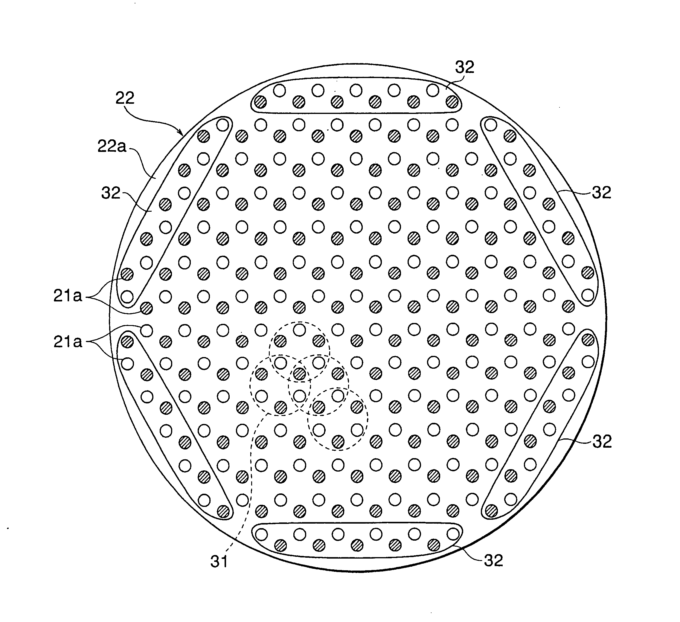
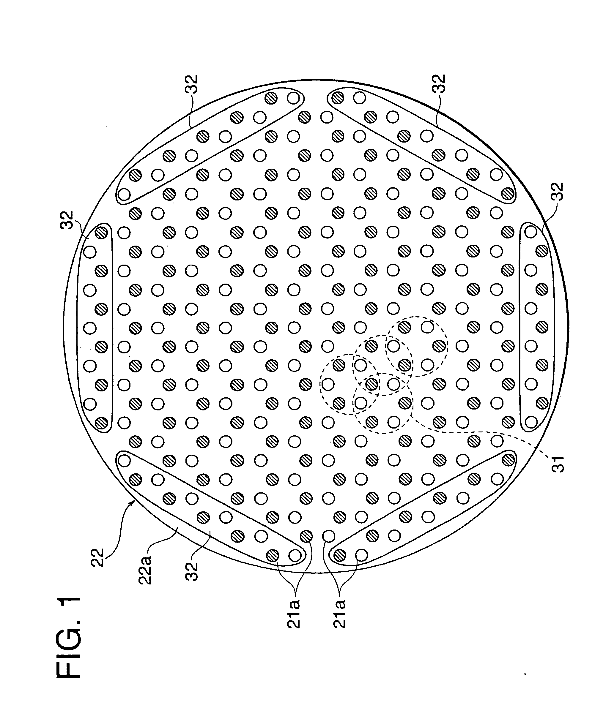
[0053]FIG. 1 shows the magnet array structure in a surface processing apparatus according to the present invention. FIG. 1 is similar to FIG. 19 and is a plan view of the magnet plate 22. In the magnet plate 22, the array structure of the large number of magnets 21 having the same shapes and same magnetic strengths is, if deeming the positions of arrangement of magnets as lattice points, a honeycomb lattice structure comprised of a large number of unit honeycomb lattices 31 forming regular hexagonal shapes by six lattice points. As explained above, the magnet plate 22 has a disk shape, so the magnets 21 attached to the surface of the disk-shaped plate member 22a are laid and fastened in unit honeycomb lattices 31 on the circular surface of the plate member 22a without gaps and without sticking out.

[0054]The magnet plate 22 has a circular plate member 22a used for fastening the magnets of the magnet plate 22. The arrangement of magnets 21 of the above honeycomb lattice structure, as ...

fourth embodiment

[0064]In the fourth embodiment, the distribution of the magnetic field strength at the required locations was controlled by preferably halving the outermost magnets 61 of the one-half length, but the plane 34 of the region where the distribution of the magnetic field strength is measured is preferably made the same height, so it is also possible to provide a support base 62 as shown in FIG. 11 to make the plane 34 a constant height.

fifth embodiment

[0065]Next, the magnet array structure will be explained with reference to FIG. 12 and FIG. 13. FIG. 12 is a plan view of the magnet plate 22, while FIG. 13 is a partial side view of part of the magnet plate 22 in section.

[0066]The magnet plate 22 according to the present embodiment has, as its basic configuration, a magnet array of the square lattice structure explained as the prior art. A large number of magnets 21 are arranged based on the square lattice structure explained above in the region from the center of the magnet plate 22 to near the peripheral edge. In this region, a large number of square lattices 131 are arranged with periodicity. In an array of magnets 21 according to this square lattice structure, the polarities of the magnetic poles of any two nearest adjoining magnets 21 are opposite and therefore N poles and S poles are alternately arranged. A point-cusp magnetic field is formed by this square lattice structure. In FIG. 12, the large number of magnets 21 are sho...


PUM

PropertyMeasurementUnit
pressureaaaaaaaaaa
diameteraaaaaaaaaa
lengthaaaaaaaaaa

Abstract

This surface processing apparatus has a reactor in which plasma is generated and a substrate whose surface is to be processed by the plasma is arranged, and a magnet plate for creating a point-cusp magnetic field distributed in an inner space of the reactor, in which the plasma is generated. The magnet plate has a plurality of magnets. These magnets are arranged by a honeycomb lattice structure in a circular plane facing in parallel a surface of the substrate. One magnetic pole end face of each of magnets is arranged at a position of each of the lattice points forming hexagonal shapes on the circular plane. The polarities of the magnetic pole end faces of two adjoining magnets are arranged to become opposite alternately. The magnet plate may be provided with a plurality of magnets arranged by a lattice structure forming a square and the magnetic force (coercive force) of some of the magnets arranged at the outermost region is reduced. Thereby, the periodicity of the point-cusp magnetic field in the inside space is maintained as much as possible even at the peripheral edge and the asymmetry of the distribution of the magnetic field at the region where the periodicity is disturbed at the peripheral edge is reduced.

Description

[0001]This is a Continuation of application Ser. No. 10 / 211,367 filed Aug. 5, 2002. The disclosure of the prior application is hereby incorporated by reference herein in its entirety.BACKGROUND OF THE INVENTION[0002]1. Field of the Invention[0003]The present invention relates to a surface processing apparatus, more particularly relates to a surface processing apparatus for processing a substrate surface using plasma. This surface processing apparatus is used for the fabrication of integrated circuits in the semiconductor industry. The surface processing apparatus has a plasma source for supplying ions, electrons, neutral radicals, etc. useful for formation of an insulating film, interconnect metal, gate electrode materials, etc. on a substrate or minutely processing the substrate surface. This plasma source creates plasma inside a reactor. The distribution of this plasma is controlled by a point-cusp magnetic field.[0004]2. Description of the Related Art[0005]The configuration of a ...

Claims


Application Information

Patent Timeline
Patent Type & Authority Applications(United States)
IPC IPC(8): C23C16/52C23C16/50H01J37/32
CPCH01J37/32623Y10T428/24H01J37/32688
Inventor EGAMI, AKIHIROIKEDA, MASAYOSHISAGO, YASUMINAKAGAWA, YUKITO
Owner CANON ANELVA CORP
Why Eureka
Try Eureka