
Configurations and Methods of Gas-Assisted Spray Nozzles

Active Publication Date: 2011-07-21
SPRAYING SYST
View PDF15 Cites 1 Cited by
  • Summary
  • Abstract
  • Description
  • Claims
  • Application Information

AI Technical Summary

Benefits of technology

[0008]The present invention is directed to configurations and methods in which gas-assisted spray nozzles are used to distribute a fluid phase (most preferably water or a water-containing fluid) into a reactor or other vessel vapor effluent as micron-sized droplets, wherein the assist gas of the nozzles is preferably a process gas used in the formation of the effluent. Moreover, use of gas assisted spray nozzles will not only improve mass / heat transfer and reliability, but will also reduce the potential for clogging and erosion / corrosion.

Problems solved by technology

While most of these systems will operate satisfactorily for their intended purpose, problems are often encountered where the gas phase includes components that can deposit on, corrode, or plug the downstream flow path.
Unfortunately, such relatively large droplet size is typically associated with reduced heat and mass transfer and a high rate of gravity settling, leading to droplet coalescence and maldistribution of the injected water.
Such problems are often associated with plugging of some exchanger tubes and concurrent under-deposit corrosion while the remaining operating tubes will be subjected to high effluent flow and erosion-corrosion.
However, such a configuration does not necessarily improve the downstream distribution of the unvaporized water.
While such design features tend to improve heat and mass transfer and distribution to at least some degree, achieving these objectives is still hampered by the undesirably large water droplets which tend to coalesce and form a stratified-wavy or semi-annular free water phase downstream of the injection point.
However, it should be noted that such nozzles at the required water flow rates require in most cases prohibitively high differential pressure (e.g., 100 to 700 psi) to produce sufficiently small droplets (e.g., micron-sized droplets).
Moreover, even if one would use such nozzles, the very small orifices of such nozzles are often easily plugged in an industrial setting, with the potential for high fluid velocity-induced erosion.
Therefore, suitably high pressure steam is typically not available for use as an assist gas in the relatively high pressure environments that exist in many hydroprocessing units.
Therefore, it should be appreciated that currently known configurations and methods for water injection in the hydrotreater / hydrocracker effluent have several disadvantages that result in reduced heat and mass transfer, non-homogenous distribution of the water droplets, and / or disruption in operation.

Method used


Image

  • Configurations and Methods of Gas-Assisted Spray Nozzles
  • Configurations and Methods of Gas-Assisted Spray Nozzles

Examples


Embodiment Construction

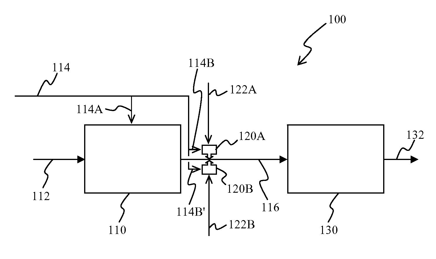
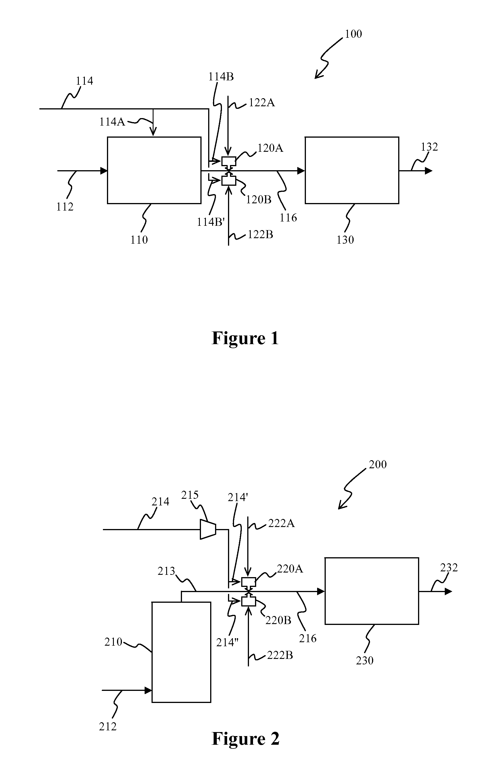
[0015]The inventors have discovered that distributed fluid injection into a gas phase, and especially water injection into a hydrotreater or hydrocracker effluent upstream of a heat exchanger is significantly improved where the fluid is injected by a gas-assisted spray nozzle as such nozzles allow formation of micron-sized droplets. As used herein, the term “micron-sized droplets” refers to droplets with an average diameter of less than 1 millimeter, more typically less than 700 micron, and most typically less than 500 micron. Most preferably, the assist gas is (or comprises) a slip stream of recycle gas and / or make-up gas from the discharge of their respective compressors in the hydroprocessing hydrotreating / hydrocracking process. With respect to the term “hydroprocessing” it should be noted that this term includes all processes in which hydrogen is used as a reactant, typically at a pressure that is significantly above atmospheric pressure (e.g., above 100 psi). For example, suita...


PUM

PropertyMeasurementUnit
Pressureaaaaaaaaaa
Diameteraaaaaaaaaa
Diameteraaaaaaaaaa

Abstract

Contemplated configurations and methods are drawn to systems in which gas assisted spray nozzles are used to distribute a liquid phase in micron-sized droplets in a device effluent at a position upstream of a second device having multiple parallel flow paths for the effluent. Most preferably, the assist gas is a high-pressure gas phase that is generated in a process upstream of the device effluent, the first device is a hydrotreating or hydrocracking reactor or distillation column, and the second device is an air cooler or heat exchanger.

Description

[0001]This application claims priority to our copending U.S. provisional application with the Ser. No. 61 / 101861, which was filed Oct. 1, 2008. This and all other extrinsic materials referred to herein are incorporated by reference in their entirety.FIELD OF THE INVENTION[0002]The field of the invention is configurations and methods for distributed injection of fluids into a gas phase or gas / liquid phase, preferably upstream of a plurality of flow paths for the gas phase.BACKGROUND OF THE INVENTION[0003]Numerous systems and methods are known in the art where fluid is injected into a gas phase using one or more spray nozzles to ensure relatively fine distribution of the fluid in the gas stream (see e.g., U.S. Pat. No. 4,568,022 or U.S. Pat. No. 6,141,986). While most of these systems will operate satisfactorily for their intended purpose, problems are often encountered where the gas phase includes components that can deposit on, corrode, or plug the downstream flow path.[0004]For exa...

Claims


Application Information

Patent Timeline
IPC IPC(8): B01J19/00B01D3/32B01F3/04B01D53/14
CPCB01D53/002B01D53/79B01D2257/304B01J4/002B01J2204/005C10G31/08C10G49/00C10G2300/207C10G2300/4012C10G2300/805C10G45/00C10G47/00C10G31/06
Inventor JACOBS, GARRY E.STUPIN, WALT
Owner SPRAYING SYST
Features
  • Generate Ideas
  • Intellectual Property
  • Life Sciences
  • Materials
  • Tech Scout
  • Unparalleled Data Quality
  • Higher Quality Content
  • 60% Fewer Hallucinations
Learn More