
Hydroprocessing system with improved cooling liquid atomization

a technology of cooling liquid and processing system, applied in the direction of hydrocarbon oil cracking, spraying apparatus, chemistry apparatus and processes, etc., can solve the problems of gas phase, droplet coalescence and maldistribution of injected water, remaining operating tubes subject to high effluent flow, erosion corrosion, etc., to reduce the potential for downstream clogging and erosion/corrosion problems, and effectively control mixed liquids

Active Publication Date: 2020-05-21
SPRAYING SYST
View PDF0 Cites 0 Cited by
  • Summary
  • Abstract
  • Description
  • Claims
  • Application Information

AI Technical Summary

Benefits of technology

The invention is about a system that uses light gases like hydrogen to atomize liquids for distribution in a reactor or other vessel. The system uses spray nozzles that improve mass transfer and cooling, reducing the potential for clogging and corrosion issues. The spray nozzles create high shear between liquid and gas phases and can adjust for changes in gas velocity. The atomizing gas pressure is at least 50 psi and is typically process gas, hydrogen-containing recycle gas, or a hydrogen-rich make-up gas. The mass flow ratio between liquid and gas is important for optimal performance.

Problems solved by technology

While most of these systems will operate satisfactorily for their intended purpose, problems often are encountered where the gas phase includes components that can deposit on, corrode, or plug the downstream flow path.
Unfortunately, such relatively large droplet size is typically associated with reduced heat and mass transfer and a high rate of gravity settling, leading to droplet coalescence and maldistribution of the injected water.
Such problems are often associated with plugging of some of the heat exchanger tubes which simultaneously propagates corrosion while the remaining operating tubes will be subjected to high effluent flow and erosion corrosion.
Since hydrogen is very light, only about 1 / 10 the mass of air typically used in gas atomizing spraying systems, it has been difficult to use such light gas in effectively atomizing liquid, such as water, into fine particles necessary for efficient cooling.
Currently known configurations and methods for water injection in the hydrotreater / hydrocracker effluent have disadvantages that result in reduced heat and mass transfer, non-homogenous distribution of the water droplets, and / or disruption in operation.

Method used


Image

  • Hydroprocessing system with improved cooling liquid atomization
  • Hydroprocessing system with improved cooling liquid atomization
  • Hydroprocessing system with improved cooling liquid atomization

Examples


Embodiment Construction

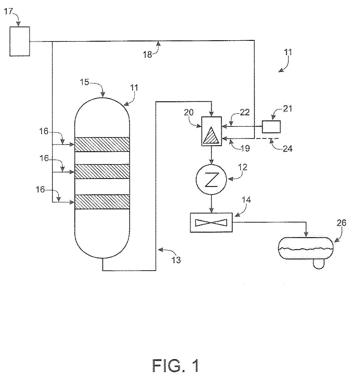
[0018]Referring now more particularly to FIG. 1 of the drawings, there is shown an illustrative hydroprocessing system, in this case a catalytic cracking system 10 in accordance with the invention. The illustrated catalytic cracking system 10 includes a fluid catalytic cracking reactor 11 the vapor stream flow of which is couple via discharge line 13 effluent coolers 12, 14. The reactor 11 has an effluent hydrocarbon feed stream coupled to a feed inlet 15 and a plurality of process gas inlets 16 coupled to a process gas supply 17. The remainder of the hydrogen gas stream from the gas supply 17 in this case is directed through line 18 to atomizing gas inlet 19 of a spray nozzle 20. Water from a wash water supply 21 is coupled to a liquid inlet 22 of the spray nozzle 20 for atomization by pressurized gas from the gas inlet 19 and direction to the downstream coolers 12, 14. Alternatively, the atomizing gas inlet 19 of the spray nozzle 20 may be coupled by line 24 for receiving recycled...


PUM


Abstract

A hydroprocessing system having a processing vessel that discharges a high temperature effluent that must be cooled prior to collection in a reflux drum. One or more gas assisted spray nozzle are provided that utilize light atomizing gas having a density of 8-15 times less than air, such as hydrogen, which preferably is the processing or recycle gas of the system. The spray nozzles are designed for the efficient atomization and direction of cooling water into a micron sized droplet distribution utilizing the light atomizing gas for affecting higher mass and heat transfer from the effluent. The spray nozzles each include a unique atomizing gas and cooling liquid passageway systems, a downstream impingement post, and a plurality of discharge orifices which sequentially breakdown the liquid into micron sized droplets as low as 500 microns and less.

Description

[0001]This patent application claims the benefit of U.S. Provisional Patent Application No. 62 / 748,993, filed Oct. 22, 2018, which is incorporated by reference.FIELD OF THE INVENTION[0002]The present invention relates generally to processing systems that utilize processing gas substantially lighter than air, and more particularly, to a spraying system for atomizing liquids with such light processing gases.BACKGROUND OF THE INVENTION[0003]Numerous systems and methods are known in which fluid is injected into a gas phase using one or more spray nozzles to effect relatively fine distribution of the fluid in the gas stream. While most of these systems will operate satisfactorily for their intended purpose, problems often are encountered where the gas phase includes components that can deposit on, corrode, or plug the downstream flow path. For example, most known hydrotreating and hydrocracking units produce an effluent gas or gas / liquid mixture having a temperature above 250 F at pressu...

Claims


Application Information

Patent Timeline
IPC IPC(8): B05B7/08B01J4/00B01J8/18C10G11/20
CPCB05B7/0869C10G2300/4006B01J8/1827B01J4/002B01J2208/00938C10G11/20B01J8/1836B01J2204/007B01J2208/00371B01J2208/00256B01J2208/00362B01J8/24B01J2208/00902C10G47/30
Inventor PATEL, BANDISH
Owner SPRAYING SYST
Features
  • Generate Ideas
  • Intellectual Property
  • Life Sciences
  • Materials
  • Tech Scout
  • Unparalleled Data Quality
  • Higher Quality Content
  • 60% Fewer Hallucinations
Learn More