Orthopedic Prosthesis

a prosthesis and orthopedic technology, applied in the field of orthopedic prosthesis, can solve the problems of knee joint cracking and wear, accelerating the wear process, and causing the menisci to crack and wear away

Inactive Publication Date: 2011-07-21
OOSTHUIZEN CHRISTIAAN RUDOLF
View PDF10 Cites 23 Cited by
  • Summary
  • Abstract
  • Description
  • Claims
  • Application Information

AI Technical Summary

Benefits of technology

[0018]the femoral articular bearing surface and the internal femoral attachment surface having a substantially uniform cross-sectional curvature at any point along the length of the anterior member, thereby providing an increased radius of the internal femoral attachment surface and an increased cross sectional line of fixation to bony tissue.
[0019]The elliptical body may be a substantially c-shaped body when viewed from the side. The elliptical body may further be a uniradial body and may provide a free range of movement of approximately 0° to 130° in situ.
[0020]The cross-sectional thickness of the anterior member may be less than 3 mm thick, and preferably 2 mm thick, at any point along the anterior member. This feature requires less invasive surgery that involves the removal of less bone from the femoral (medial or lateral) condyle.
[0023]The femoral component may have a raised medial edge relative to its lateral edge for movably abutting a corresponding formation provided for on the tibial component, thereby to prevent the femoral component from rotating about an anterior-inferior axis.
[0025]The femoral internal surface may define a suitable surface texture, such as a roughened surface texture for facilitating bony tissue adhesion thereto, while the femoral articular bearing surface may have a highly polished surface for minimizing frictional contact. The roughened surface texture may be fine or rough surface irregularities, The roughened surface texture may further extend onto the surface of the peg formation. The femoral internal surface may further include a mesh, attached to and slightly proud of the femoral internal surface. This mesh may be made from plastics or metal, such as polyethylene or titanium, or a combination thereof.

Problems solved by technology

Problems may arise with knee joints due to various factors, including injury, old age, and genetic predisposition to degenerative diseases.
Osteoarthritis can occur after years of normal use of the knee, causing the menisci to crack and wear away.
Alignment problems such as bow-legs and so-called “knock knees” may speed up this wear process.
In both conditions, once the menisci are destroyed or worn away, as the case may be, the femoral condyles will rub against the tibial plateaus, leading initially to pain and swelling and a limited range of movement, and ultimately to a fusing of the joint.
The Oxford knee may have a disadvantage of a limited range of movement and a potential for bearing insert dislocation when the knee is flexed beyond approximately 130°.
Furthermore, axial rotation of the knee while the knee is flexed to substantially 90°, or extended to 0°, may result in pronounced spacer / bearing insert overhang, and may further restrict the practical utility of the Oxford knee.
Furthermore, the size and thickness of the femoral component of prior art prostheses, including the Oxford knee, requires a large amount of bone to be removed from the femoral condyle in order to accommodate the prosthesis.
This is hardly suitable and because of the limited lifespan of the prior art prostheses (10-15 years), a replacement of same may be indicated at that time.
These represent some of the additional disadvantages associated with the prior art prostheses.
Such prostheses unfortunately usually last for only about 15 years on average, and thereafter a so-called full knee replacement is required.

Method used


Image

  • Orthopedic Prosthesis
  • Orthopedic Prosthesis
  • Orthopedic Prosthesis

Examples


Embodiment Construction

[0043]In the drawings, like numerals refer to like parts, unless otherwise indicated.

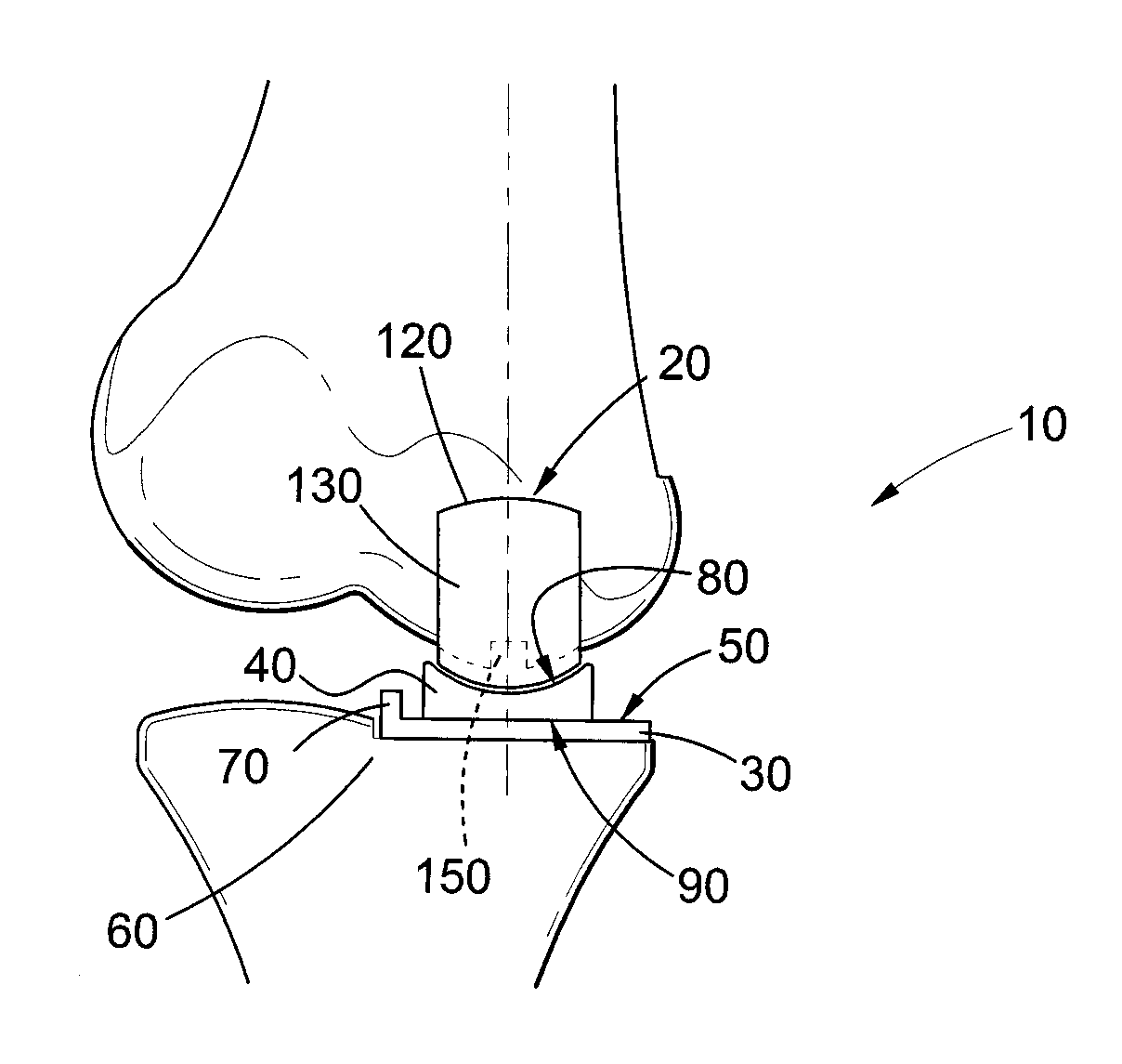
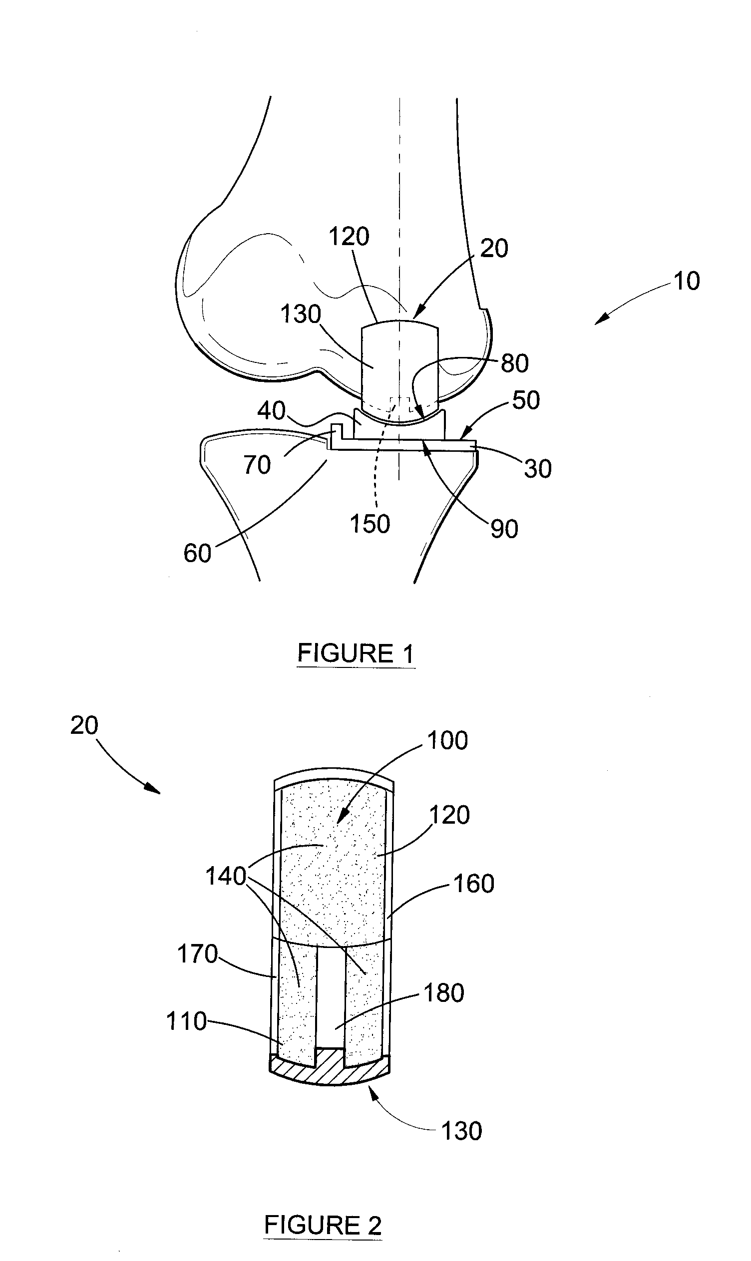
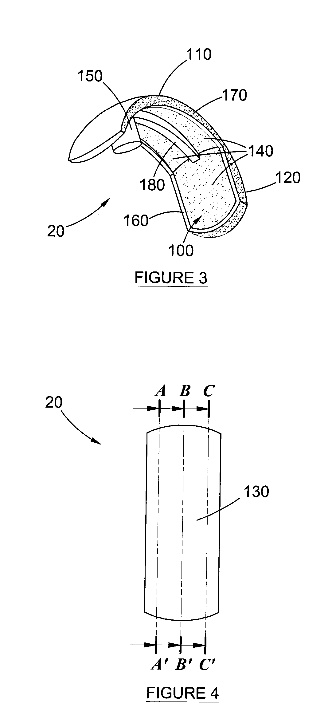
[0044]Referring firstly to FIG. 1, reference numeral 10 generally refers to an improved orthopedic prosthesis according to one form of the present invention. The orthopedic prosthesis 10 comprises a femoral component generally indicated by reference numeral 20, and a tibial component 30. A spacer bearing 40 is positioned between the femoral component 20 and the tibial component 30.

[0045]The tibial component 30 is of the type conventionally utilized in the art and consists of a tibial upper bearing surface 50 in a substantially planar D-shape when viewed in plan view (not shown). The tibial planar upper bearing surface 50 receives the spacer bearing 40 in a floating arrangement. Typically the tibial upper bearing surface 50 is highly polished in order to optimize free movement of the spacer bearing 40 thereon and to reduce friction therebetween. The tibial component 30 further has a lower attachment ...


PUM

PropertyMeasurementUnit
thicknessaaaaaaaaaa
thicknessaaaaaaaaaa
lengthaaaaaaaaaa

Abstract

According to one aspect of the present invention, there is provided an orthopedic prosthesis (10) suitable for resurfacing chondral deficient surface areas in knee joints, including a tibial component (30) defining a tibial articular bearing surface (50), a femoral component (20) defining a femoral articular bearing surface (130) and a spacer bearing (40) disposed therebetween, the femoral component further including an elliptical body having an anterior member (110) and a posterior member (120), and an internal femoral attachment surface (140), the femoral articular bearing surface and the internal femoral attachment surface having a substantially uniform cross-sectional curvature at any point along the length of the anterior member, thereby providing an increased radius of the internal femoral attachment surface and an increased cross sectional line of fixation to bony tissue.

Description

FIELD OF THE INVENTION[0001]This invention relates to an orthopedic prosthesis. More particularly, this invention relates to an improved resurfacing prosthesis of the knee, and linked thereto an improved surgical approach to knee replacements.BACKGROUND OF THE INVENTION[0002]Various types of knee prostheses / prosthetic joints are known in the field of orthopedic surgery, and these are widely used by orthopedic surgeons. In particular, knee prostheses have been developed since the pioneering efforts of Sir John Charnely, and in particular his revolutionary hip replacement techniques introduced during the 1960's.[0003]In order to understand the background to the present invention and the rationale behind knee replacements or revisions, it is necessary to briefly describe the basic anatomy of a knee. A knee joint is formed by the articulation of a femur with a tibia and fibula. The femur has at its substantially cuboid lower extremity two oblong eminences, a lateral and medial condyle. ...

Claims


Application Information

Patent Timeline
Patent Type & Authority Applications(United States)
IPC IPC(8): A61F2/38
CPCA61F2/38A61F2/3859A61F2002/30878A61F2310/00796A61F2002/30909A61F2002/3895A61F2310/00023A61F2002/30884
Inventor OOSTHUIZEN, CHRISTIAAN RUDOLF
Owner OOSTHUIZEN CHRISTIAAN RUDOLF
Why Eureka
Try Eureka