Crawling automated scanner for non-destructive inspection of aeropace structural elements

an automated scanner and structural element technology, applied in the direction of mechanical measuring arrangements, mechanical roughness/irregularity measurements, instruments, etc., can solve the problems of inability to achieve or too expensive and time-consuming, manual scanning of structures is time-consuming, labor-intensive, and prone to human error and/or other health problems for technicians

Active Publication Date: 2011-07-21
THE BOEING CO
View PDF13 Cites 108 Cited by
  • Summary
  • Abstract
  • Description
  • Claims
  • Application Information

AI Technical Summary

Problems solved by technology

In many cases, structures must be inspected in the field because it is either not feasible or too expensive and time-consuming to transport the structure to an off-site laboratory for the inspection.
Thus, manual scanning of structures is time-consuming, labor-intensive, and prone to human error.
Furthermore, manual scanning may cause fatigue and / or other health problems for technicians, such as Repetitive Motion Disorders.
While the M.A.U.S. system is portable, provides fast inspection rates, and employs numerous types of sensors, such as those mentioned above, the linear track on which it moves limits its use to structures where the track can mount to the structure and not interfere with the inspection area.
Where its linear track attaches to the structure, the region underneath the track cannot be inspected during a scanning pass.
The M.A.U.S. system is not adaptable to shorter chordlength aerospace airfoil structures, such as rotorcraft blades, aircraft propellers, smaller winglets, narrow tail sections, and windmill blades.
Thus, it may not be feasible to use the M.A.U.S. system for shorter chordlength aerospace airfoil structures.
The M.A.U.S. also cannot do through-transmission ultrasonic inspection, so structure that requires this modality, such as some honeycomb structure, cannot be inspected using it.
During flight operations, damage can occur in these structures due to impact, moisture damage, sand erosion or degradation.
Rotorcraft maintenance is a cumbersome endeavor for military and commercial operators.
But tap testing is crude and highly operator dependent such that many blades are dismantled and repaired when they are acceptable for continued use, and worse yet, some blades are passed that aren't flight worthy.
Tap testing is also very slow and manually intensive, does not provide any images of the damage or a permanent record that can be stored, printed or sent electronically to a remote expert to be evaluated.
Likewise, hand held NDI scanning devices are limited by operator skill as was discussed previously.
Another technique for assessing the condition of airfoil structures is automated scanning (among which the MAUS is a sub-set), but this type of requires tracks or other mounts, the devices used are not expandable, and they cannot scan leading edges or highly contoured areas.
Nor are they capable of through-transmission inspection, and may require the structure to be removed in order for it to be inspected.

Method used


Image

  • Crawling automated scanner for non-destructive inspection of aeropace structural elements
  • Crawling automated scanner for non-destructive inspection of aeropace structural elements
  • Crawling automated scanner for non-destructive inspection of aeropace structural elements

Examples


Embodiment Construction

[0022]Embodiments of the present disclosure now will be described more fully hereinafter with reference to the accompanying drawings. However, many different embodiments are contemplated and the present disclosure should not be construed as limited to the embodiments set forth herein; rather, these embodiments are provided so that this disclosure will be thorough and complete and better convey the scope of the disclosure to those skilled in the art.

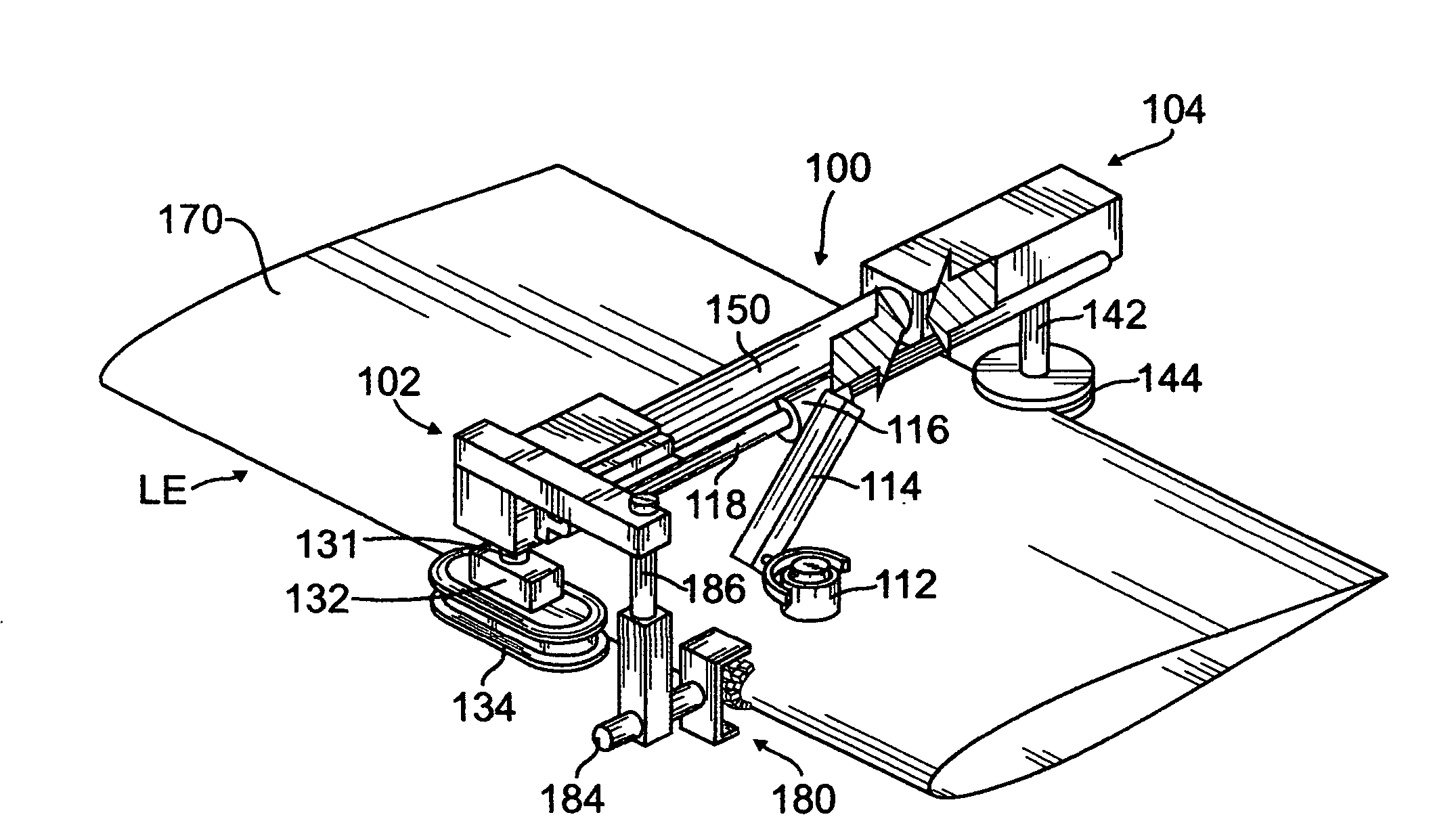
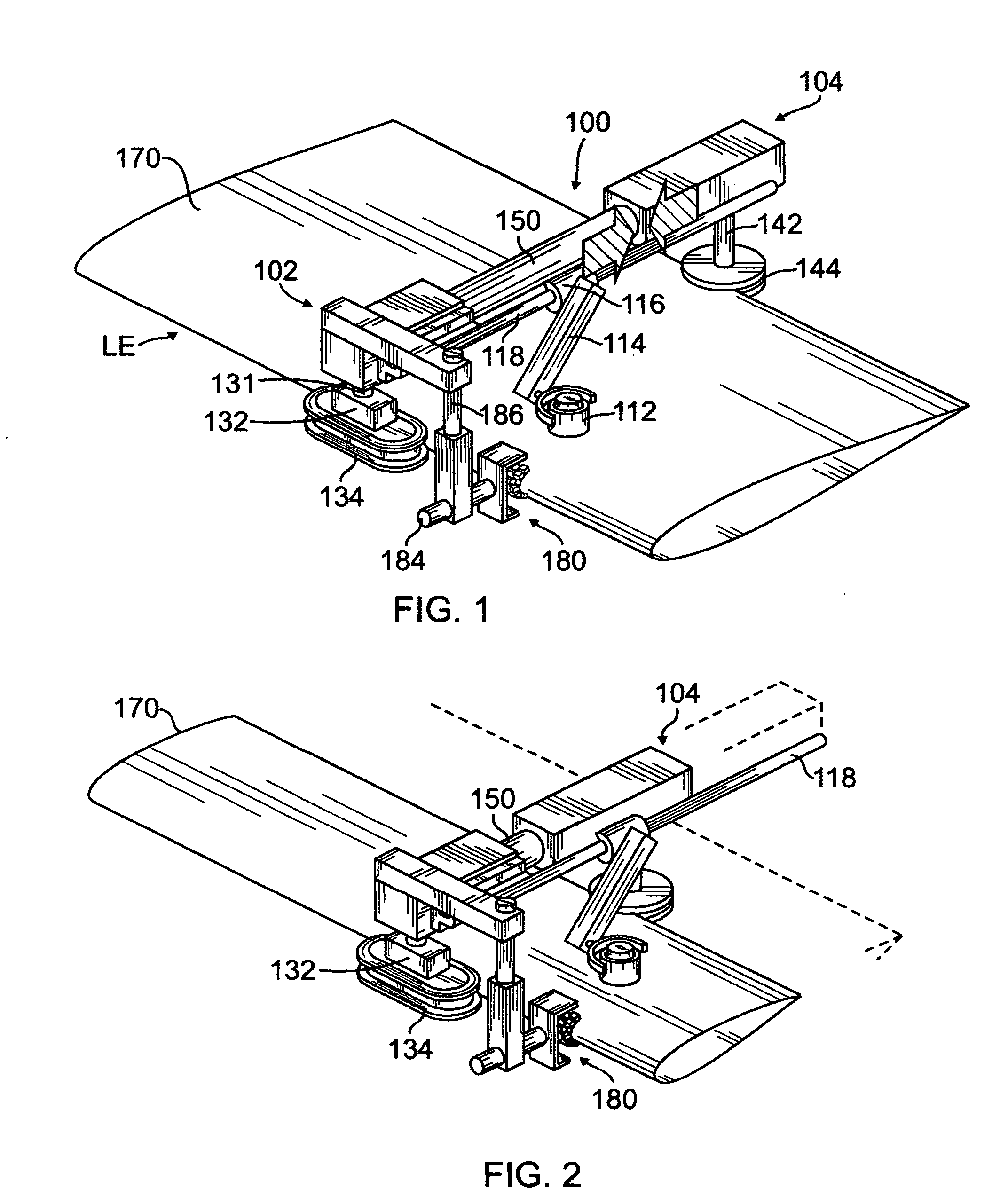
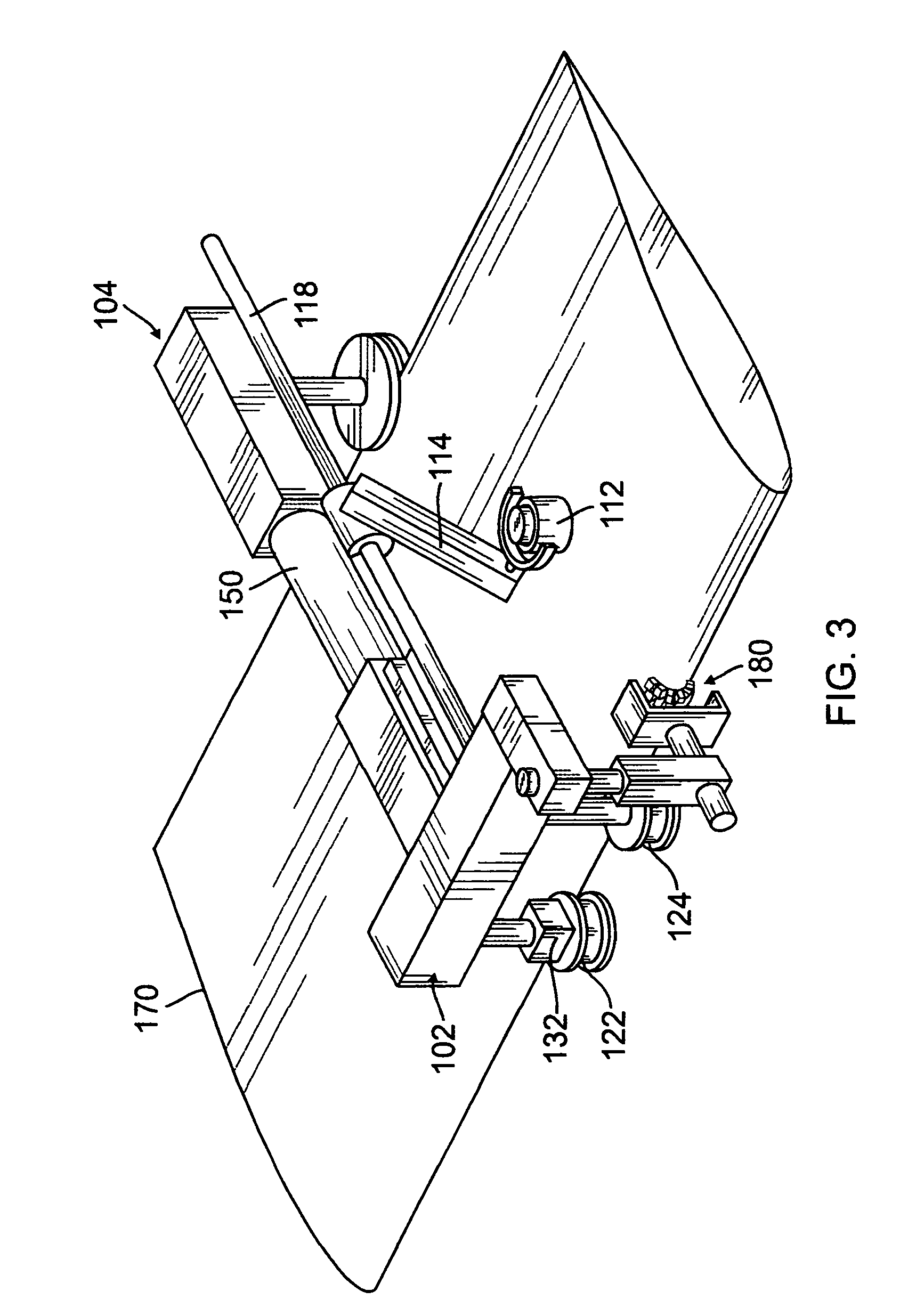
[0023]In its broadest sense, this disclosure presents an autonomous, self-propelled, expandable, and adjustable apparatus for inspecting in-service aerospace structures such as rotorcraft blades, aircraft propellers, smaller winglets, narrow tail sections, and windmill blades for structural damage by “crawling along the length of the structure using the structure itself as the track, and employing scanning sensor mechanisms such as ultrasonic pulse echo, eddy current arrays, resonance arrays, and bondtester or laser probes, to access the ...


PUM


Abstract

Apparatus for non-destructive inspection of structural elements or workpieces, in particular those having an airfoil configuration, that moves a scanning sensor across the width (span) of a structural element or workpiece for the purpose of detecting structural damage. In one embodiment, the apparatus simultaneously traverses the length (chord) of the structural element or workpiece. In another embodiment, the apparatus includes a guide rail that encompasses the structural element or workpiece and the scanning sensor travels along the guide rail from a first location at an upper rear region, to the front, of the structural element or workpiece, and then around the leading edge toward the lower rear region. The apparatus includes a processor and a display device to display the processed, sensed, information.

Description

FIELD OF THE DISCLOSURE[0001]The present disclosure relates generally to the field of non-destructive inspection of aerospace structural elements, and more particularly to a non-destructive inspection apparatus that mounts to, and travels along, an aerospace structural element, such as a rotorcraft blade, an aircraft propeller, winglets, a projectile fin, an aircraft tail section, a windmill blade, etc., while inspecting and determining the existence of structural defects and / or damage.[0002]Non-destructive testing of structures involves thoroughly examining a structure without harming the structure or requiring significant disassembly of the structure. Non-destructive testing is advantageous for many applications in which a thorough inspection of the exterior and / or interior of a structure is required. For example, non-destructive testing is commonly utilized in the aircraft industry to inspect aircraft structures for any type of internal or external damage to the structure. Metall...

Claims


Application Information

Patent Timeline
Patent Type & Authority Applications(United States)
IPC IPC(8): G01B5/28
CPCG01M5/0016G01M5/0075G01N29/043F01D5/005G01N29/265G01N2291/2694Y02T50/672G01N29/225B64F5/60Y02T50/60
Inventor HAFENRICHTER, JOSEPH L.GEORGESON, GARY E.WOOD, NANCY L.
Owner THE BOEING CO
Why Eureka
Try Eureka